While working on recreating an “ancient” (read: 60-year-old) logic circuit type known as resistor-transistor logic, [Tim] stumbled across a circuit with an unexpected oscillation. The oscillation appeared to be random and had a wide range of frequency values. Not one to miss out on a serendipitous moment, he realized that the circuit he built could be used as a chaotic oscillator.
Chaotic systems can be used for, among other things, random number generation, so making sure that they do not repeat in a reliable way is a valuable property of a circuit. [Tim]’s design uses LEDs in series with the base of each of three transistors, with the output of each transistor feeding into the input of the next transistor in line, forming a ring. At certain voltages close to the switching voltages of the transistors, the behavior of the circuit changes unpredictably both in magnitude and frequency.
Building real-life systems that exhibit true randomness or chaotic behavior are surprisingly rare, and even things which seem random are often not random enough for certain applications. [Tim]’s design benefits from being relatively simple and inexpensive for how chaotic it behaves, and if you want to see his detailed analysis of the circuit be sure to visit his project’s page.
If you want to get your chaos the old fashioned way, with a Chua circuit, look out for counterfeit multipliers.


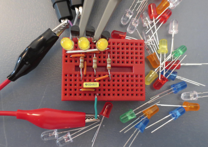
The cropped title photo (for the blog) doesn’t show the transistors, so I started reading to find out how LEDs, resistors, and a capacitor was causing the oscillations.
[Tim] test various LEDs and transistors and showed the X-Y plots of the various combinations.
Good work!
Something like this could be used as learning module for oscillators.
Threw me for a second as well but you can see the three transistors at the top edge of the breadboard. Oscilloscope leads can be seen attached to the collectors of the first two.
It’s an interesting effect, but for purpose of random numbers it’s probably not better than avalanche noise.
It’s really pretty close to the SAME as avalanche noise. but these days, LEDs are cheaper than zener diodes.
None of the LEDs or transistors are in avalanche configuration, and without careful analysis of the circuit, it’s hard to say how much high frequency noise is amplified.
Usually, noise generators use a reverse biased base-emitter junction for the avalanche effect, followed by another transistor for amplification. No zeners and no LEDs, just a few caps and resistors.
It’s actually far from the same. Avalanche noise is mostly random. The chaotic oscillator will show repeatable patterns in some specific conditions, depending on the supply voltage. The chaotic character of the system is not really randomness, but rather unpredictability.
You can replicate an avalanche diode with a reversly biased base emitter junction of any transitor, btw. High hfe should work best.
That makes me wonder, other than price, the LEDs would be influenced by the amount of light in the environment falling on them, where the zener diodes would likely be coated such that they do not.
If that small effect is being amplified, and is likely always changing by the tiniest amounts, I’d be very curious to know if using zeners really would be the same or not.
Since the LEDs emitting light would change the current generated by the other LEDs, that is yet another form of interaction and influence that might end up being significant compared to not being there in the first place.
Yes, absolutely. In fact, all junction diodes and transistors function as photodiodes when exposed to light, although the spectral sensitivity varies between device types. I remember doing a project using (don’t laugh) CK-722 transistors, which were encapsulated in clear plastic which was painted black. But the top and bottom weren’t painted, and the whole circuit changed characteristics when exposed to light.
So not only will light change the DC operating point of the circuit, but if the light is MODULATED, as it would be for any fluorescent or most LED lighting, you would have an AC component that is decidedly non-random. So yeah, best paint the LEDs or put them in a light-tight box.
Boy you’re really showing your age with the old raytheon part. I paid 26 bucks for my firsr 722 and even more for the 721. The transistor was actually a tiny little thing put into a white epoxie like material that made it look much larger than the actual device. The white filler also served as a lead stress relief. The 2N107 and 2N170 GE’s were the first hobbiest devices were also being used in the day. They were all good sources of noise!
Not QUITE as old as you might guess. The problem is that I was learning electronics from library books that were at least a decade old, and these were calling out CK-722, 2N107, and 2N109, for the most part. In actual fact, at the time I was using these, the 2N3904, 2N3906, 2N2222, and 2N2907 were available, I just didn’t know what they were. And by that time, the first-generation hobby transistors were being sold in grab bags, since they were obsolete.
> (read: 60-year-old) logic circuit type known as resistor-transistor logic
It is still useful *today* as you can build with a transistor and some resistors. It can go where regular logic can’t – higher voltages/currents.
I2C and CAN come to mind :)
I am wondering what the yellow rectangular component is and where it would be in the accompanying circuit in the blog.
The circuit as drawn is all DC coupled, and if you make a loop with gain that’s DC coupled throughout, it’s most likely going to quickly be stuck at the supply voltage or ground. The component is probably a capacitor, for AC coupling the output to the input of the loop.
Thanks for the reply. Any rule of thumb or formula for calculating its value and what type of cap it would be?
I’m an ME and want to get into electronics at this level, so the next step is to start reading some of the books that I bought 5 years ago and never touched.
I traced the breadboard and tied it to the circuit and that makes sense. Time to fire up the RIGOL scope for the first time as well.
Boy, am I embarrassed. First, I said that the circuit would stick at either the supply voltage or ground. Neither would be the case, since there are three inverting amplifiers, making this what is called a phase shift oscillator. And second, in the article, the author says that the yellow rectangle is a decoupling capacitor, which would be a capacitor from the supply to ground, typically be a ceramic capacitor in the 0.1 to 1.0 microfarad range. In any case, I was wrong, and the natural frequency for the oscillator would be that at which each of the amplifiers shifted the phase by about 60 degrees, so that the total phase shift around the loop would be 720 degrees. The randomness would be around this natural frequency, based on the noise introduced by the LEDs, which as someone else pointed out, is similar to avalanche noise.
I am a fellow ME too. Just stick around here and you will learn a ton by osmosis. Check out righto.com as well.
BTW, The schematic on the link does not show a capacitor.
Yes. That’s what I meant when I said the circuit as drawn was DC coupled throughout.
Doh!
It is DC coupled only part of the time when the transistor in front is off. If the transistor before it is On, then the LED Anode is connected close to Gnd. It is no longer conducting DC, but act as a capacitor with its junction capactance.
It’s a 100n decoupling capacitor connected to the supply. Removing it would probably have no effect.
Thanks – just posted above and saw your comments. Will try both ways.
Thanks – just posted above and saw your comment.
> (read: 60-year-old) logic circuit type known as resistor-transistor logic
I still have my RTL Cookbook.. RTL was taught the first year of college. The next year, they switched from RTL to TTL, and from Slide Rules to Calculators. Thanks for making me feel old!
Why’d they skip DTL ?
Because DTL is functionally almost identaical to TTL. TTL was just a way of fitting DTL circuits into less silicon, by using multiple-emitter transistors to form NAND gates, rather than a single transistor plus multiple diodes. In fact, DTL and TTL could be intermixed, since they used the same supply voltages and had roughly the same high and low thresholds and input currents. TTL also added totem pole outputs (i.e., a push-pull output rather than a passive resistor pull-up and a transistor pull-down), which improved rise time, and thus propogation time, greatly.
Hmm, life in general seems like a conditionally unstable chaotic oscillator, with the paradox we observe it with potentially chaotic ideas of our send of self projected as consciousness ;-)
Thanks for post, practical & easy to build, tough to appreciate, perplexing to factor into phenomenology…
I’d like to see a frequency spectrum of some of those oscillators. I’m guessing harmonics are all over the place.
If an oscillator output is random, is it really an oscillator?
In the February 1971 issue of Popular Electronics, Don Lancaster had the cover project, the Psych-Tone. It used RTL, shift registers to generate a pseudo-random sequence to control the frequency of an audio oscillator. So a random note electronic music instrument.
I like that thought. Also thank you for that article, I am going to have to give that a read. It is right up my alley :)
Does anyone know if this may work at audio rates instead of the MHz rate we see in the captures? This could be great for Eurorack synthesis.
Leo Chua
http://www.chuacircuits.com/howtobuild1.php
I would like to add to the appreciation of Don Lancaster’s contributions to our understanding of so many things that were new to us at the time. I also particularly appreciate, and frequently cite (with attribution) his dedication of the TTL Cookbook “to the yeah-but…”