If you’ve ever built a crystal radio, there’s something magical about being able to pull voices and music from far away out of thin air. If you haven’t built one, maybe you should while there’s still something on the AM band. Of course, nowadays the equivalent might be an SDR. But barring a computer solution, there are not many ways to convert radio waves into intelligence. From a pocket radio to advanced RADAR to a satellite in orbit, receiving a radio wave is accomplished in pretty much the same way.
There are, however, many ways to modulate and demodulate that radio wave. Of course, an AM radio works differently than an FM radio. A satellite data downlink works differently, too. But the process of capturing the radio wave from the air and getting them into a form ready for further processing hasn’t changed much over the years.
In this article, I’ll talk about the most common radio receiver architectures you may have seen in years past, and next week I’ll talk about modern architectures. Either way, understanding receiver architectures will help you design new radios or troubleshoot them.
Comparing Radios
If you were going to grade a receiver, there are several things that are of prime importance:
- Selectivity – There are lots of radio waves swimming around you. A selective receiver can pull out just the one you want. This is particularly noticeable when you have two strong stations near each other in frequency.
- Sensitivity – The signal coming in from an antenna is probably very weak. Receivers have different levels of sensitivity and a more sensitive receiver will pick up a weaker signal.
- Noise floor – Receivers will have a certain amount of noise that will cover up a weak signal. Obviously, the lower the noise floor, the better reception for weak signals.
That Crystal Radio
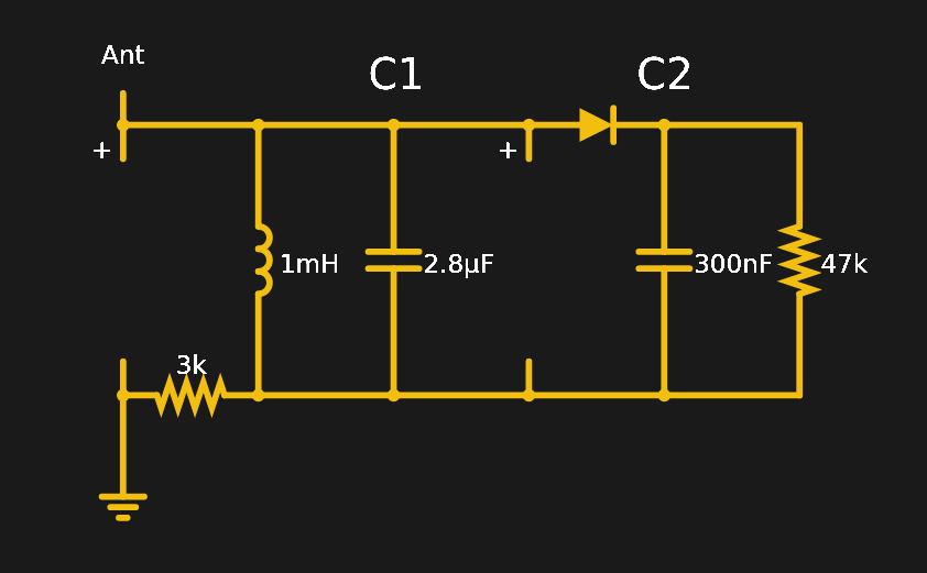 The crystal radio is one of the simplest of radio designs, operating without an amplifier and getting its power from the radio signal itself. The crystal radio you built as a kid is very similar in design to the earliest radio receivers. A tuned circuit picks the frequency and a detector — usually a diode — demodulates the signal directly. If you do the math, the tuned circuit has low impedance to all frequencies except the one you’ve tuned into. The coil and the capacitor effectively cancel each other out at that frequency, and — if the components were perfect — present an infinite impedance to the signal of interest. That means all other signals will attenuate compared to the main signal.
The original design of these radios date to when there was no good way to amplify signals, so it doesn’t. That means you need a strong signal and a big antenna. You also benefit from a solid ground connection. Never built a crystal radio? My favorite simulator, Falstad, has a crystal radio you can simulate. The simulation relies on the program’s antenna component which has AM modulated signals at 3 kHz, 2.71 kHz, and 2.43 kHz.
While the tank circuit offers some selectivity, it isn’t very good. The sensitivity of this receiver is also not very good. You don’t generally see circuits like this in practical applications. However, some people like to try to push the best possible performance from a crystal radio, like Chris Wendling does in the video below. If you decide to build one, you might want to start with something more modest.
TRF and Reflex
A step up from the crystal radio is the TRF or tuned radio frequency architecture. With TRF, you basically have a crystal radio with some amplifiers ahead of the detector that amplify better at some frequencies than others — essentially filters with gain.
If you’ve ever seen a 1920s- or 1930s-era radio with numerous tuning knobs on the front panel, that’s probably a TRF radio. You had to tune each dial to the correct frequency.
The TRF is not a bad design, especially if you could figure out how to change the tuning of the amplifiers from a single control. But it is on the lower end of the performance spectrum. However, many inexpensive radios still use TRF because a 1972-era chip and its successors cram an entire TRF radio into a small IC package.
The device looked like a transistor and at least one variant had 10 transistors inside. It provided the RF amplification, detection, and even automatic gain control using only six external components. The original chip expected you to have an external coil and capacitor, a few filter capacitors, and a few resistors to both power the device and provide the automatic gain control (AGC) action. Later models also had some audio amplification stages.
Obviously, one three-legged device appealed to companies that wanted to make small cheap radios. Speaking of cheaper, another old version of the TRF is the reflex receiver. It dates back to 1914, although it was independently discovered at least one other time in the early 20th century.


The idea is to use one amplifier for amplifying both RF and the audio output (see the accompanying block diagram and schematic). This is possible because the radio frequency is so much higher than the audio frequencies and you can use filters to steer the signals through the same tube. These are generally not seen much anymore, but it is an interesting solution to the days when saving a single active device was a major cost savings.
Modern Times
While you don’t see many crystal and reflex radios these days, there are still TRF designs floating around, especially based on the many ICs that work that way. However, the regenerative receiver is probably a better choice if you want to make a very simple but workable radio. There are also direct conversion receivers — you see them a lot with software defined radio setups. The gold standard is the superheterodyne receiver, which is what an overwhelming number of devices use today.
I’ll talk about those architectures, and a few others, in the next article. Meanwhile, see what you can do to build that crystal radio. If you don’t have the right parts, you can make most of them from common items. If you don’t have a diode, you could use a razor blade and a pencil, as [RimstarOrg] — the YouTube channel of Hackaday’s own Steven Dufresne — shows in the video below.
Acknowledgment: Most of the pretty pictures of block diagrams and schematics were adapted from public domain sources on Wikipedia, particularly from [Chetvorno]. What a great resource.


The AM radio IC in to92 ‘transistor’ package mentioned is the ZN414, aka MK484, aka TA7642.
They are fun things to experiment with. A complete radio with headphone output consists of something like 10 parts in total.
Pretty decent sensitivity though selectivity can be worse than with a superhet receiver.
You can also use them in a superheterodyne, where you can use it as a detector with a nice load of amplification and some AVC functionality. In most designs you have 2 IF filters/stages, if you use the mk484 you can probably get away with just one.
Early? Not a coherer in sight… https://en.wikipedia.org/wiki/Coherer
Thanks for that link! I’m just getting into radios and I had never heard of that device before.
Very interesting what was accomplished with so little.
You said ‘tank circuit’. You know what you meant, I know what you meant, but I tell ya, kids these days ..
I’d like to tank circuit city for letting me use their bathroom.
This.
A crystal radio, was the reason I got into electronics almost 50 years ago. When I was 12, my teacher brought a crystal radio to school. Of course, in the 70’s, everything ran “on batteries”. We were amazed that it needed NO batteries. I asked him how it worked without batteries. He said why don’t you see if you can find out why and let me know. That one question, started me on my journey into electronics. When I was in junior high school, we only had “analog google” (library) and I read up on ohm’s law, and a bunch of other stuff. By the time I was a teenager, I was installing car radios in cars for friends, working in a television repair shop. After high school, went to a 2 year college for electronics. I’ve been in electronics ever since. Still love it!
I used galena found along railroad tracks to make my catwhisker. There was about as much on the AM band in the 60s as on over-the-air tv, now,.or as much real news as in entertainment news broadcasts of the USoA. My snowsled HBO saw only 15 minutes of use after hours making the hand cut pcb. There is no intelligent life out there, on any known channel.
Well there’s a ton of old radio serials on librivox.org which also has a phone app, as well as archive.org so you can listen to The Saint over again or something.
In the crystal radio schematic, the tank circuit contains a 1 millihenry inductor and a 2.8 microfarad capacitor. As far as I can tell that has a resonant frequency of around 2.9 kilohertz. I don’t think that circuit does what you think it does…
Perhaps 1uH would make more sense, that’d put it right about 3MHz, the old ’80 meters’ territory. Used to be where to go to listen for CW (Morse code, kids), though I thought CW on a crystal set just gave you clicks on make/break
Idk. It’s been a long time since I last tried something like that
AM tuner caps were always 365pF.
he 1mH is about 450T on a 1″ coil, but good luck getting a tuner cap at 2.8uF. :P Someone would need a dial-a-cap box just for that.
Those approx 1″x1″x 2/3″ transparent plastic cased ones were, and were very common in the generic AM radios of the 60s through 80s. However, other types did exist that ranged from 280 to 600 (Maybe wider range, that’s just stuff I encountered)
Keep in mind this is from the Falstad simulator which runs very slowly. From the help:
The inductor and the capacitor C1 are tuned to 3 kHz, t… By experimenting with the value of C1’s capacitance, you can pick up two other “stations” at 2.71 kHz and 2.43 kHz.
Your LF filter values are too large, giving Tau of about 15 ms. That’s way too much for voice – cutting off all of the mid and high frequencies. 300 pF capacitor is far better that 300 nF, with 47 KOhm load.
It isn’t receiving voice it is receiving a very specific signal that the simulator introduces through the antenna. It’s purely for simulation.
Alrighty then. Thanks for clarifying.
From the post: My favorite simulator, Falstad, has a crystal radio you can simulate. The simulation relies on the program’s antenna component which has AM modulated signals at 3 kHz, 2.71 kHz, and 2.43 kHz.
That brought back memories..
When I was 7 years old, in 1972, I went to the library and came across a Ladybird book, ‘Making a Transistor Radio’ by G.C.Dobbs. I still have the copy I bought 48 years later. It really captured my imagination and at the tender age of 7 I decided that was what I wanted to do – electronics. I built the radio and some bits worked, some didn’t but that didn’t matter – the crystal set certainly did.
Fast forward 48 years and I’ve had a career in electronics and software, have a ham license, and still love playing with and designing/building my own electronics stuff. And all thanks to the humble crystal set.
Well if you’re still interested there is a copy of that book online.
https://archive.org/details/MakingATransistorRadio
I still have my original copy..
I didn’t have a copy, thanks for sharing :-)
Can you say anything about the receiver technology prevalent in WW I-era commercial equipment, such as the Titanic gear they’re trying to salvage?
Various types were used. Almost every ship had a crystal receiver as a back up. AFAIK the Titanic used a Marconi magnetic detector as a main detector. Audio amplification was only occasionally used. If it was present, it usually was in the form of a Brown amplifier – a special kind of electromechanical amplifier. You can compare it to an earphone, with a carbon microphone attached to it – but more refined of course.
Stations using early CW equipment, would use tikker receivers. Essentially a crystal receiver with a mechanical chopper to modulate the unmodulated DC coming from the detector.
A wideband Marconi spark transmitter with rotary gap (as opposed to the narrow band stuff made by Telefunken and other manufacturers) was used as the transmitter.
In WW1, the first tube equipment was just about being tested. Tubes were often not hard vacuum like today, but contained some gas. This made them noisy, very temperamentful and with low gain.
Developments went so incredibly fast, that the difference between a 1910 receiving station and a 1920 one, is about the same as seeing a Nokia 3310 and the newest smartphones of today.
Howard Armstrong got his patent for the regenerative receiver in Oct 1914. He got his superhet patent in 1918, and his superregen patent in 1921. Obviously his work predates the patents by a bit, actual useage only developed slowly.
I’m not sure when spark started disappearing, or when “crystal radios” took over from the coherer.
I remember thinking maybe five years ago that how did Fessenden broadcast voice in 1906 if coherers were still common (since they’d not work with voice),though when I brought it up in another forum, someone suggested it was less the spontaneous event that the books suggest, but a deliberate test with suitable receivers in place.
Of course, the sinking of the Titanic caused new and more complicated radio regulations. Not a technical change, but more the foundation of radio as we know it than previous rukes.
The basic Crystal radio schematic, once you calculate the right values for the components, works like a charm also with fm signals. Only the digital radio will be a show stopper for this amazing experience.
“The gold standard is the superheterodyne receiver, which is what an overwhelming number of devices use today.”
Nope. The largest number of “radios” sold today are in car and truck consoles, consumer television sets, and mobile phones (not necessarily in that order), and almost all of those are typically direct conversion quadrature SDR designs.
So they derive from Armstrong’s regenerative receiver? When it oscillates, it becomes a direct cinversion receiver.
Big difference between “in use today” which is, in fact, still overwhelmingly the superhet, vs. “sold today” which is tending more toward SDR in first-world countries. It’s a big world out there, and there are still a lot of superhets being produced.
Commented just to agree with this.
To the guy that says Superhets are more common, well, possibly.
But Direct conversion SDR type receivers are everywhere. Most people just don’t know it.
I started with “The Rocket” crystal set, sold back in the early 60’s. Cousin Brucie on WABC, easy!. But after graduating to a Knight Kit tube Regen by mid-60’s, any mode I wanted, it could get. Just adjust the Regenerative control. AM, of course, SSB and CW after you advanced the regen knob. Other modes such as RTTY if you were careful. This old 12AT7 based radio would get Radio Australia consistently on 31 and 25 Meters any morning.
Yep, another Armstrong innovation!
I have tried to figure out why the diode is necessary and why the signal after the filter is not enough. Can anyone offer m ed a hint?
It’s risky to give you an answer inside this community (too many experts with no mercy) but I’ll give a try.
The diode is fundamental because it works as a simple envelope demodulator. Wikipedia is your friend: https://en.wikipedia.org/wiki/Envelope_detector
About the signal power: nowadays there are so few AM stations that are unlikely to live close enough to one of them to get a strong signal. This is the reason why I built an FM crystal radio instead (still not to easy to make it work, depending on your distance from a transmitting station). It uses the same circuit because, given that the tank is selective enough and that you are slightly off the central frequency, you will have a slope detector (https://www.electronics-notes.com/articles/radio/modulation/fm-frequency-demodulation-slope-detector-discriminator.php) that, roughly speaking, converts FM to AM.
I tried but my comment disappeared…
Again, in short:
– the diode serves as envelope detector (https://en.wikipedia.org/wiki/Envelope_detector)
– AM stations are rare nowadays. If you are far, the signal is weak
– try make an FM crystal radio as an alternative. Odds are that you have one very close by. The circuit is the same but the tank doubles as slope detector (https://www.electronics-notes.com/articles/radio/modulation/fm-frequency-demodulation-slope-detector-discriminator.php)
Again, in short:
– the diode serves as envelope detector (check wikipedia)
– AM stations are rare nowadays. If you are far, the signal is weak
– try to make an FM crystal radio as an alternative. Odds are that you have one very close by. The circuit is the same but the tank doubles as slope detector (check google)
Sorry, I had to strip out the links to make my comment pass through. Scheisse filters.
now my previous comment is back. What a mess!
Flankendemodulation (flank demodulation?) is a cool thing.
Crystal radios are easy to build.
Excellent crystal radios are not!
Scrap your cheap industrial diodes and get a real detector crystal.
It provides much better audio and sensitivity.
What is a ” real detector crystal “? I’ve tried galena with no luck. The 1n34 seemed to work the best for me. Silicone diodes don’t seem as good as germanium
Reflex receivers were a popular hobby project, after transistors became available. I have a whole anthology of such designs, from early 1970s. Unfortuantely, it’s only in Polish. One impressive design there is an actual reflex superhet, based on ONE transistor. It was reprinted from an East-German magazine “Funkamateur” (“Superhet mit einem Transistor” R. Peschlow, Funkamateur April 1967, p. 193) – I saw someone is selling these old copies of Funkamateur on DVDs, all in German of course…