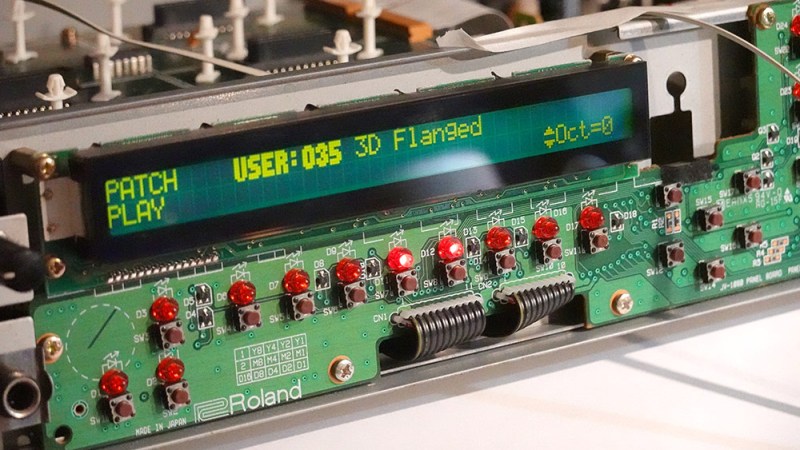
[Mitxela]’s repair of a Roland JV-1080 (a rack-mounted 90s-era synthesizer) sounds simple: replace a broken rotary encoder on the front panel. It turned out to be anything but simple, since the part in question is not today’s idea of a standard rotary encoder at all. The JV-1080 uses some kind of rotary pulse switch, which has three outputs (one for each direction, and one for pushing the knob in like a button.) Turn the knob in one direction, and one of the output wires is briefly shorted to ground with every detent. Turn it the other way, and the same happens on the other output wire. This is the part that needed a replacement.
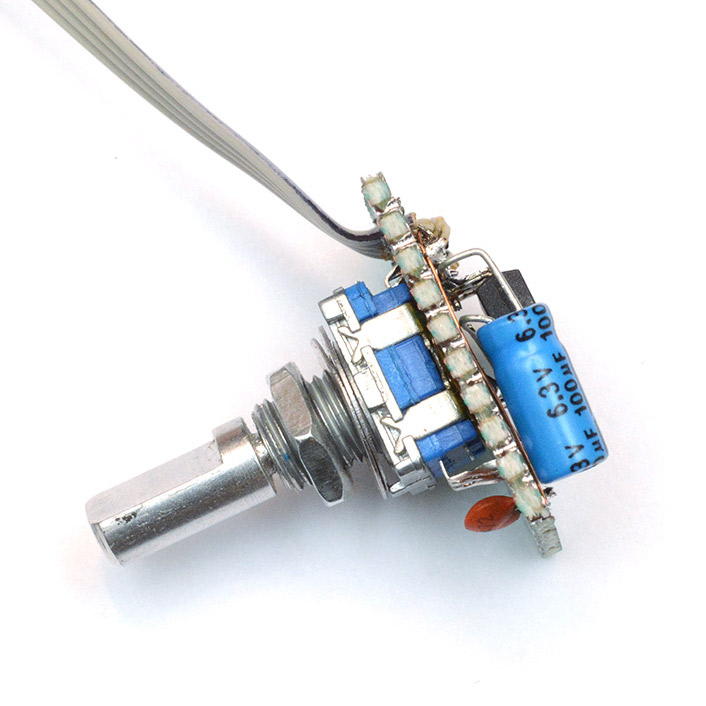
Rather than track down a source for the broken part, [Mitxela] opted to replace it with a modern rotary encoder combined with an ATtiny85 microcontroller to make it act like something the JV-1080 understands and expects. There was an additional wrinkle, however. The original rotary pulse switch is an entirely passive device, and lives at the end of a four-conductor cable with no power provided on it. How could the ATtiny85 be powered without resorting to running a wire to a DC voltage supply somewhere? Success was had, but it did take some finessing.
For the power, it turns out that the signal wires are weakly pulled up to +5 V and [Mitxela] used that for a power supply to the microcontroller. Still, by itself that wasn’t enough, because the ATtiny85 can easily consume more current than the weak pullups can source. We really recommend reading all the details in [Mitxela]’s writeup, but the short version is that the ATtiny85 does two things.
First, it minimizes its power usage by spending most of its time in sleep mode (consuming barely any power at all) and uses an interrupt to wake up just long enough to handle knob activity. Second, the trickle of power from the weak pullups doesn’t feed the ATtiny directly. It charges a 100 uF capacitor through a diode, and that is what keeps the microcontroller from browning out during its brief spurts of activity. Even better, after browsing the datasheet for the ATtiny, [Mitxela] saw it was possible to use the built-in ESD protection diodes for this purpose instead of adding a separate component.
It’s a neat trick and makes for a very compact package. Visit the project’s GitHub repository to dive into the nitty gritty. In the end, a single assembly at the end of a 4-wire connector acts just like the original passive component, no extra wires or hardware modifications needed.
When opening older hardware it’s never quite certain what will be found on the inside. But at least [Mitxela]’s repair duties on this synth didn’t end up with him tripping out on LSD.


I had a similar idea – buttons in public places can be replaced with proximity sensors without the need to provide additional wire to power them. Such a module can have 2 pins and be connected instead of the button.
Uhm… I would have used a LS7183 quadrature converter, but I guess these days we have more attinys than quadrature converters handy.
Using a LS7183 would be a way more elegant solution, at least in my opinion.
No need to program anything, no software bugs and great power consumption.
Today we solve everything with an MCU…
And how much current does your LS7183 draw?
According to the datasheet, 30 μA is the typical average. The inside of an LS7183 is very simple, a pair of flip flops and a pair of NOR gates IIRC, and is wat you would had find inside a rotary encoder of this type.
LS7183 specifies a maximum output pulse of 140us, while Mitxela clearly states that the synth doesn’t properly register pulses under 1ms. It’s possible this is why he didn’t use it.
I think it has probably more to do with the fact that most people are not aware of quadrature converters, while most of us have microcontrollers. I only know about the LS7183 because I had to use for a project 10 years ago – I did a quick look and is either discontinued or is very hard to get a hold of it, and quite expensive to boot.
I want to clarify that my first statement was not meant to be sarcastic. It’s quite amazing we can emulate most simple ICs with a ultra-cheap microcontroller, honestly.
PS: Regarding the specific comment, you can adjust the output pulse by putting a resistor on pin one. For the TR-909 that I repaired, the 500ns pulse was enough – although was not the same machine, so maybe 0.5ms would be not enough.
When I think “encoder”, USDigital is at the top of my list. Among many other things, they have the LS7183 readily available is DIP and SOIC at about $3 each. Not cheap, but compared to micro controller and custom firmware for a one-off…
https://www.usdigital.com/products/accessories/interfaces
[mitxela] has a lot of other projects worth looking at: https://mitxela.com/projects/hardware
i especially like the mini synths he manages to build
Someone should’ve gone to eBay ;) The place is absolutely awash with identical encoders. [Shameless plug] I used two of them in my Steampunk Laptop — https://hackaday.com/2019/06/09/homebrew-laptop-makes-a-statement-with-a-steampunk-theme/ — and — https://hackaday.io/project/164620-the-homebrew-steampunk-laptop-v2
I’d bought three off eBay… the left-side one adjusts the volume up/down, smack it to toggle mute status. The right-side one, which (surprisingly) I hardly ever actually use, is supposed to scroll up/down like a mouse wheel, with a wheel-click when you pop it in. That said, I suspect that the pop-in switch doesn’t work on that one, because it’s never actually done anything when I’ve poked it… and one or the other of them (I forget now lol) didn’t work at all when I first stuck it in there! I had to swap it out. Good thing I bought three! FWIW, they’re driven by an Arduino Pro MIcro clone running the QMK keyboard firmware. What can I say, it worked…
Worth noting, fixing the synth with the proper part (or, rather, a horribly-cheap clone of it) wouldn’t have been an article-worthy hack, or really a hack at all for that matter — but it is/was quite doable, and would’ve been far simpler.
Beautiful example of signal powering a microcontroller. I didn’t realize until now that flowing through the protection diodes was a safe and legitimate method. Thank you for taking the time to write up your build.
I probably would have just bodged in a power wire, but this is more elegant. In future, I will consider this approach.
It depends on the ESD structure in the chip. Some will conduct quite a lot of current continuously without issues but others use a triggered structure to short out the ESD, which does not allow this way if powering.
It’s a pulse switch. Made by Alps. Originals are expensive. Compatibles, not so much:
https://m.aliexpress.com/item/32778955771.html
A five stars review that translates (all the page text appears in language-from-geolocated-IP) back to “Encoder does not work. None of them. They are absolutely rubbish. Very bad quality.” Five. Of. Five. Stars.
Using ALPS site, they say only JP shops have SRBM1L0800, one of them for 551 yen, other 1156 yen, that’s around 5.20-10.50 dollars per switch. Or keep sustaining that Chinese by paying 32 and see if the lotto gives you 3 or more that work?
Looks like recycling “refurbished” switches by shipping them back is a good business. Buyers beware, no cries if wallet and/or ecosystem keep on walking to the grave.
Probably he tried to use them as normal quadrature encoders.
Great stuff! The writeup is amazing.
Hmm. I bought a bag of them and they all work great. Very simple but clever mechanism. They are pulse switches, which are indeed quite different to rotary encoders. It really helps to know what you are looking at, and what you are talking about.
Hi Andrew, would you be interested in selling one of these? Trying to fix an SE70 and don’t want to buy a bag of encoders (or have to program a uC)
I’d love to, but it’s not practical.
I am more impressed by that bold font on what looks like a standard character LCD. I know they have 8 or 10 RAM slots for custom chars but that must really take some effort to populate the custom char map data for the specific characters required to be shown, including numbers, as I have never seen a char LCD with that font before…
I shouldn’t of said more impressive, parasitically powering a micro for inline manipulation of data to masquerade as a legacy device is very impressive. I just like display electronics, and that font is pretty cool.