[Blake]’s interest in building keyboards happened naturally enough — he was looking for a new project to work on and fell into the treasure chest that is the mechanical keyboard community. It sounds like he hasn’t built anything but keyboards since then, and we can absolutely relate.
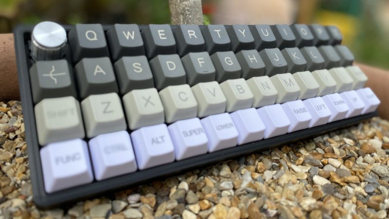
 This tidy 40% ortholinear is [Blake]’s third build, not including macro keebs. It’s based on an open source case and plate from Thingiverse, and uses an Arduino Pro Micro running the popular QMK firmware to read input from 47 Gateron blues and a rotary encoder.
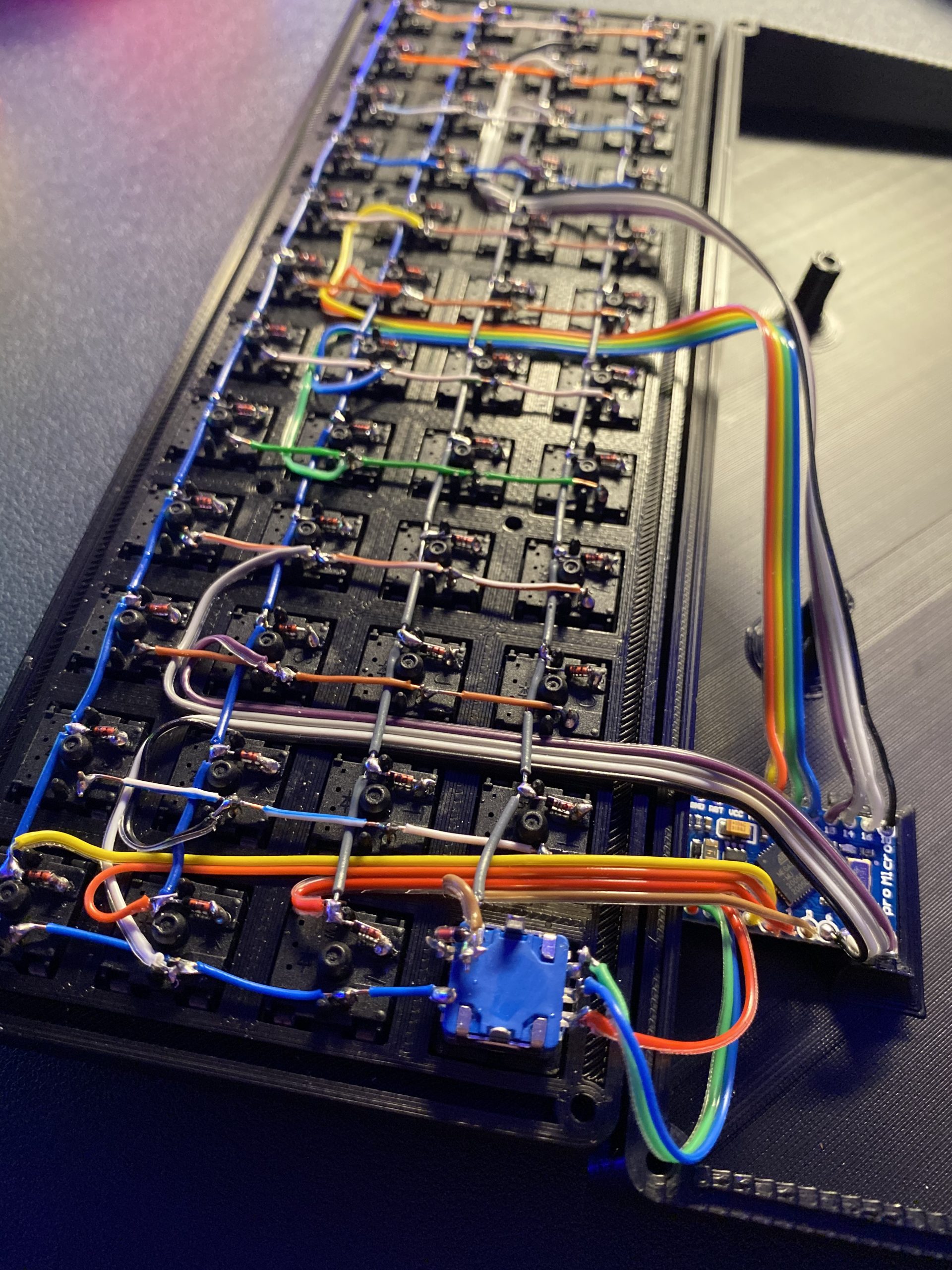
We particularly like the double rainbow ribbon cable wiring method [Blake] used to connect each row and column to the controller. It looks beautiful, yes, but it’s also a great way to maintain sanity while programming and troubleshooting.
Keyboard builds can look daunting, even at 40% of standard size. But as [Blake] discovered, there are some really good guides out there with fantastic tips for hand-wiring in small spaces. And now there is another well-written guide with clear pictures to point to.
Looking to split from the standard rectangle form factor but don’t know what to go with? Divine your next clacker with this split keyboard finder.
Thanks for the tip, [jrdsgl]!


Can people please stop using the small wire jog in circuit schematics to indicate a jump over a crossing wire? It is so ugly and quaint. The schematic drawing rules at the end of the book “Art of Electronics” results in beautiful schematics
I can’t find any schematics in any of the things linked above?
Artwork on second key down on the left.
I think that’s a bow and arrow. It’s a shortcut for firing off emails. zip zip zip!
Personally, I’m more bothered by the keyboard hacker slang which just comes across as sounding childish, but to each their own.
I have no problem with “moist” but hearing “keeb” drives me nuts for some reason, go figure.
Possibly because the former is an actual word in the English language?
Sure, because beautiful schematics are far more important than clear unambiguous at a glance schematics. 😏🤷♂️
Depends on what standard you follow. The jump wire could also be read as a single winding coil. I’ve learned at school that crossing wires at right angles is not connected while a 3 way split is connected. So if you offset one incoming line at the crossing you get two 3 way split that are connected. No junction circles are used that way. But most electronic CAD software use junction circles to indicate connection.
Care to describe it at least for those who don’t have the book?
I’ve seen schematics where two lines that cross without the jog are connected. I’ve seen ones where unless they have the dot they are not connected. I hate ambiguity so I prefer using both the jog and the dot.
Appendix B.2 p1101 of the good book (3rd edition) states:
-Wires connecting are indicated by heavy back dots; wires crossing, but not connecting, have no dot (don’t use a little half-circular “jog”; it went out in the 1950s).
-Four wires must not connect at a point; i.e., wires must not cross _and_ connect. You sometimes see this rule violated, but it’s poor practice (because a missing or under-sized dot is a different circuit).
looks like I need to update my drawing habits!
This keyboard looks really nice, but the fact that the rows aren’t staggered means typing on it would take quite a while to get used to. Staggered is just so much nicer.
It’s really just a matter of taste. For years I struggled to type in the dark without a backlit keyboard but a 5×12 ortho changed that for me. due to the small size of the grid my spatial awareness can locate most key positions. I’d probably be faster with a 4×12 as the linear numbers strip still slows me down vs using a numpad layout one handed.
You know if it’s a programmable board, you could program a keypad layer, that you could activate with a press of “strange” keys.
Why do all the keys have diodes? This is normally not the case, only perhaps for SHIFT, ALT and CTRL to avoid ghost presses.
For the sake of NKR, which they will likely never use. However, diodes are so cheap there is no reason not to use them.
It’s actually super useful if you play with Plover, and these small ortho boards are just perfect for it.
I think it’s to avoid ghosting for n-key rollover.
It is only really low end keyboards that have left out the diodes for some years – any decent keybaord will have diodes on each key to stop phantom keys and phantom key blocking.
Also, following your logic, on a keyboard where any key can be SHIFT, ALT or CTRL, you need diodes everywhere.
is to small. minimum are 20*5
;: pgup down
second trouble are backlight, very not intuitive.
too small, but 85% is ok for exzample https://klawiatura.files.wordpress.com/2020/08/kl.jpg
I’m going to leave: https://1.bp.blogspot.com/-rRS_TOYuIQQ/XhRERox3moI/AAAAAAABEB0/uTThutO8H9o8HK-sdNgzOKC1-gIdyEFoACLcBGAsYHQ/s1600/Capture.png here, from https://blog.gboards.ca/2020/01/weird-keyboards-programmable-keyboards.html
As some food for thought. You can press more than one key at a time you know.