Sometimes, projects are borne out of neccessity; a fix for a problem that needs to be solved. Other times, they’re done just for the love of creation and experimentation. [ultraembedded]’s FPGAmp media player falls under the latter, and served as a great learning experience along the way.
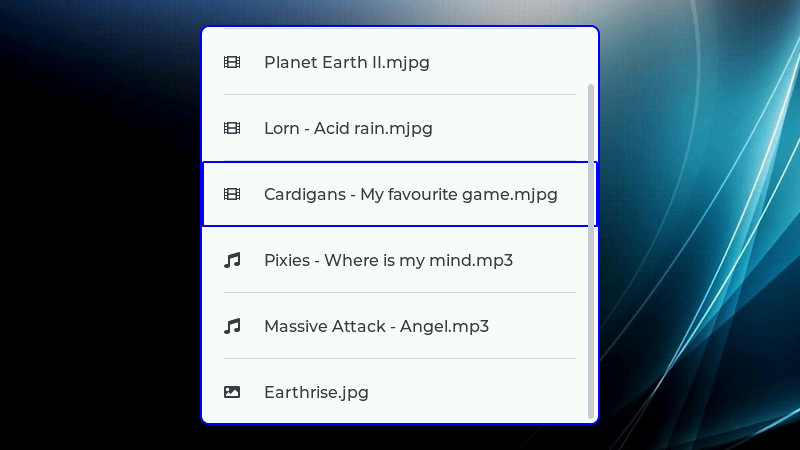
The aim of FPGAmp is to play back a variety of media files on the Arty A7 development board, based around the Xilinx Artix-7 FPGA. Capable of playing back MJPEG video at 800 x 600 resolution and 25 fps, it’s also able to play back MP3s as well for stereo audio. Demonstrating the device on Twitter, [ultraembedded] notes that the method of using an LED to do SPDIF optical audio output isn’t legit, but does work. A later update switches to using a dedicated audio output board with the Arty A7 platform, featuring an excellent song from The Cardigans.
Using a RISC V processor core and a hardware JPEG decoder, we imagine [ultraembedded] really sharpened their FPGA skills with this project. Particularly in the wake of the sale of ARM to NVIDIA, RISC V continues to gain relevance in the hardware community. We were lucky enough to feature a keynote at last year’s Supercon, with Megan Wachs speaking on the technology. Video after the break.
Thanks to the #LVGL user interface library, my @DigilentInc #ArtyA7 #FPGA based media player project is now looking half decent. Plays 800×600 25fps video, MP3's and JPEG stills. All RTL and firmware sources now available on Github: https://t.co/TTG7huzyZW pic.twitter.com/6UWy2UXOfW
— ultraembedded (@ultraembedded) September 20, 2020


I think you misinterpreted the Twitter “via an LED” comment about the SPDIF implementation. He’s not saying it was not legit. SPDIF had two specified physical interfaces, coaxial cable via RCA connector, or optical via TOSLINK. TOSLINK itself is pretty sketchy, in that it did NOT use laser diodes, but LEDs. The bit rate was low enough that lasers were neither necessary nor helpful. So while many people assumed that “fiber-optic” meant laser, it just wasn’t the case. TOSLINK was just a marketing ploy to make people think they were getting something cutting-edge, but really the only advantage over coaxial was that with the optical connection you get isolation, so no possibility of ground loops. The comment “via an LED” just meant that he did this with an optical interface rather than coaxial.
We seem to have a similar taste in music, shame our skillset differs – mine being lacking!!😒
The hacky part here is that he is using a debug LED as a toslink transmitter! The board doesn’t have a traditional toslink optical module (with red LED and appropriate housing for the fiber coupler) so he is literally holding the optical fiber up to the LD0 green debug LED on the FPGA dev board.
The versatility of what people can do with the debug LEDs on devices never ceases to amaze me. First it was using them as a serial tty for dumping firmware, and here it is running at 3.1Mbaud PCM.
In an fpga, Yes. But utilizing a microprocessor in the fpga ruined it for me. I was expecting pure hdl when I read that title.
To be fair, the CPU is very lightly loaded, which is good as it is running at 50MHz! The high data flows (SD -> JPEG decoder, JPEG decoder -> framebuffer) are done using DMA hw (data mover engines). The CPU is periodically configuring the DMA transfers, dealing with FAT32 intricacies, feeding the audio subsystem and running the user interface.
Personally I see nothing wrong with using a soft CPU in an FPGA. Running a GUI, reading files off a filesystem, etc could be accomplished in pure HDL by utilizing state machines. And what is a microprocessor if not a general purpose programmable state machine? And don’t forget, he could have done JPEG decoding in software on the microprocessor but instead that is implemented in Verilog. He’s doing all the right things, parallelizing operations by using hardware accelerators where needed and making his life easier by running sequential operations where they belong, in software on a soft core processor. Great project!
“basedd around the Xilinx Artix-7 FPGA” – basedd … Spell checker out of operation?
Thanks for the correction!
Are you aware that your tone comes across as abrasive?