When the Prusa i3 MK3 was released in 2017, it was marketed as being “bloody smart” thanks to the impressive number of sensors that had been packed into the printer. The update wasn’t really about improving print quality over the MK2, but rather to make the machine easier to use and more reliable. There was a system for resuming prints that had stopped during a power outage, a thermometer so the firmware could compensate against thermal drift in the inductive bed sensor, RPM detection on all of the cooling fans, and advanced Trinamic stepper drivers that could detect when the printer had slipped or gotten stuck.
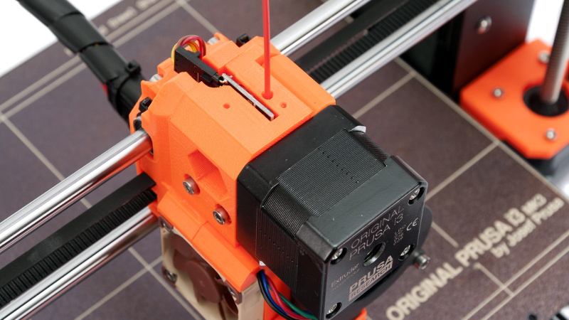
But the most exciting upgrade of all was the new filament sensor. Using an optical encoder similar to what you’d find in a mouse, the Prusa i3 MK3 could detect when filament had been inserted into the extruder. This allowed the firmware to pause the print if the filament had run out, a feature that before this point was largely unheard of on consumer-grade desktop 3D printers. More than that, the optical encoder could also detect whether or not the filament was actually moving through the extruder.
In theory, this meant the MK3 could sense problems such as a jammed extruder or a tangle in the filament path that was keeping the spool from unrolling. Any other consumer 3D printer on the market would simply continue merrily along, not realizing that it wasn’t actually extruding any plastic. But the MK3 would be able to see that the filament had stalled and alert the user. The capabilities of the optical filament sensor represented a minor revolution in desktop 3D printing, and combined with the rest of the instrumentation in the MK3, promised to all but eradicate the heartbreak of failed prints.
Fast forward to February of 2019, and the announcement of the Prusa i3 MK3S. This relatively minor refresh of the printer collected up all the incremental tweaks that had been made during the production of the MK3, and didn’t really add any new features. Though it did delete one: the MK3S removed the optical encoder sensor used in the MK3, and with it the ability to sense filament movement. Users would have to decide if keeping the ability to detect clogs and tangles was worth giving up all of the other improvements offered by the update.
But why? What happened in those three years that made Prusa Research decide to abandon what promised to be a huge usability improvement for their flagship product? The answer is an interesting look at how even the cleverest of engineering solutions don’t always work as expected in the real-world.
A Hands-Off Approach
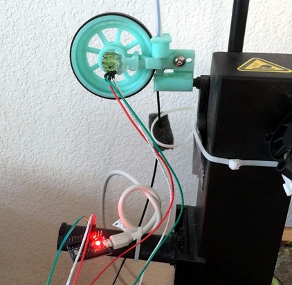
Of course, Prusa Research weren’t the first to try and tackle the problem of jammed filament detection. Hackers had already been cobbling together their own solutions for years by the time the MK3 was released, but most of them used a more direct approach. The most common way was to simply push a wheel against the spool or the filament itself, the rotation of which can easily be detected through a rotary encoder or Hall-effect sensor.
But the problem with this idea is that it puts additional drag on the filament, which can introduce variations in the extrusion rate that ultimately impact print quality. Users chasing perfect extrusion have developed various low-drag spool holders for exactly this reason. Adding drag into the system, even if it would allow for the detection of stalled filament, would be a non-starter for many users.
The beauty of the optical sensor was that it could “see” when the filament was moving without actually touching it. Again, Prusa Research didn’t come up with this idea. There had already been attempts to visually inspect the filament as it entered the extruder, though the goal was generally to compensate for varying filament thickness.
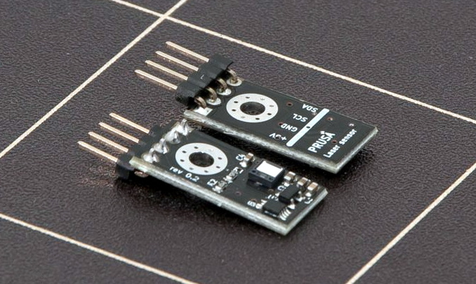
What Prusa Research did do was come up with a low-cost open hardware sensor that combined these established ideas to create an accurate non-contact filament speed sensor. By rights, you’d expect that by now every 3D printer manufacturer on the planet would have spun up their own variation of this little sensor and bolted it onto their entry level machines.
Which they certainly would have done eventually, if the sensor had actually worked as intended.
Blinded By Science
To be clear, the optical filament sensor in the Prusa i3 MK3 did work. They wouldn’t have shipped the machine out if it hadn’t. It even worked pretty well… most of the time. But it had a few pretty serious issues that really only became apparent as users spent some quality time with the machine. Even before the release of the MK3S and its physical removal of the sensor, many users had simply opted to turn the optical sensor off in the firmware settings due to issues that simply became too common to ignore.
The first and most obvious problem was that the sensor had occasional difficulties seeing light colored filaments, and an even worse time with translucent ones. This alone wasn’t really a huge problem for many users; a quick stroll through Thingiverse will show you that most 3D printer owners stick with black, blue, or red filament to begin with. But as users put more time in on the MK3 and started using less common colors, it became clear that not all filament was equal in the eyes of the printer.
Unfortunately, the second issue further compounded the problem. While there was a clear attempt to recess the sensor into the extruder body, dust still managed to find its way in. To a degree this was unavoidable, as the gears of the extruder invariably generate bits of plastic dust as they do their thing. The official maintenance procedure advised users to keep an eye out for dust and particle buildup around the extruder gears, but it doesn’t mention checking the sensor. While removing the sensor and cleaning it without tearing the whole extruder apart isn’t terribly difficult, it’s not what anyone would call user friendly. It’s certainly not the sort of thing you’d do on a whim, especially if there’s no mention of it in the maintenance guidelines.
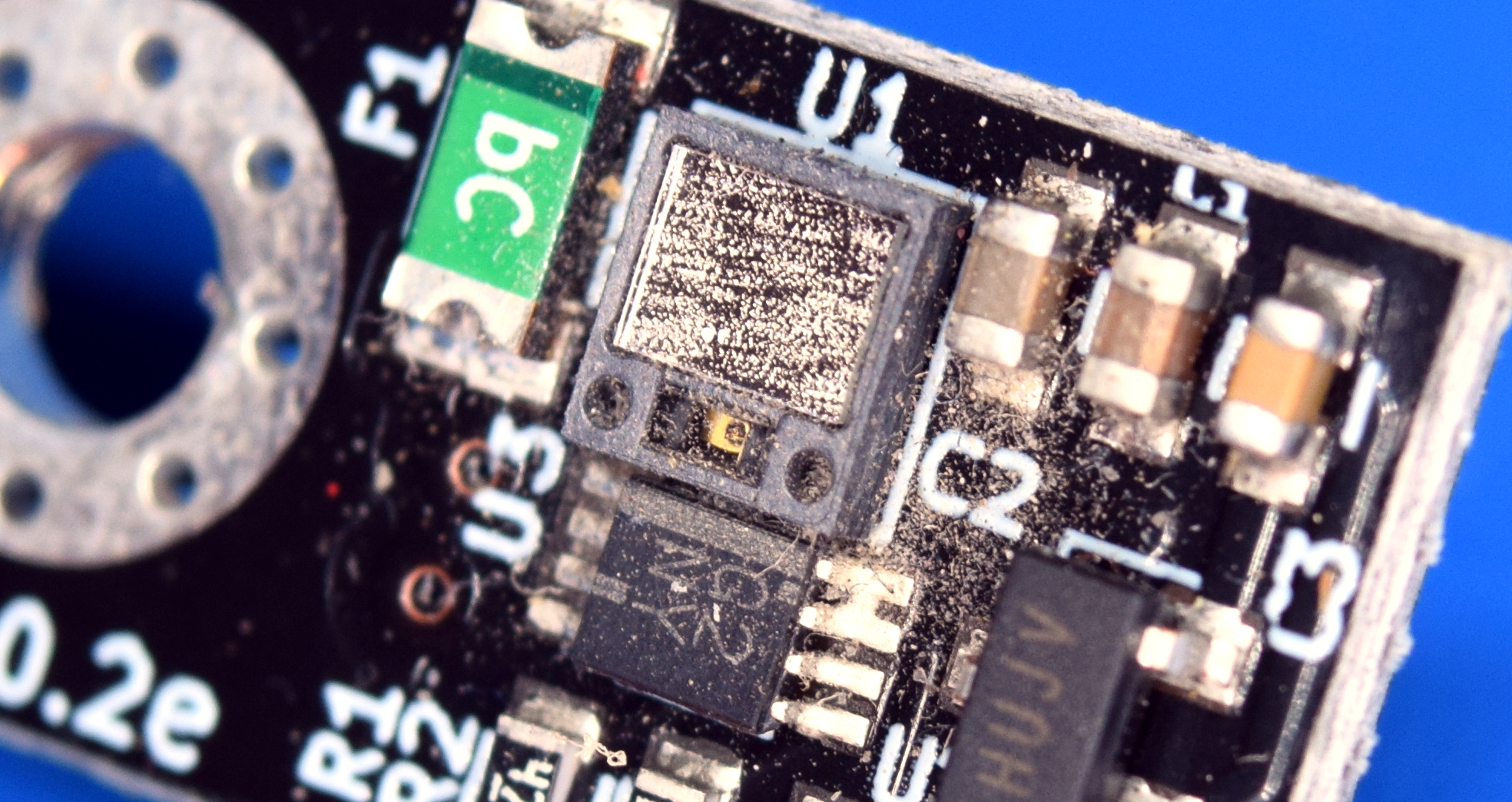
After awhile, this coating of dust would start to impact the sensor’s ability to see the filament. Problems that you ran into only occasionally started becoming daily occurrences. You might notice that inserting filament into the extruder wouldn’t always trigger the auto-load function, requiring you to engage it manually. In the worst case, the printer could suddenly decide that the filament had disappeared and stop the print. This was annoying enough if you were in the same room with it, but if you did long prints overnight or while you were out of the house, it could be a huge waste of time.
Back to the Drawing Board
Amending the maintenance procedure to have users remove and clean the optical sensor every few months could have helped the situation, but frankly, it would have been a stopgap measure at best. Clearly the sensor wasn’t up to the challenge. The accuracy wasn’t high enough even under ideal conditions, and it introduced a weak spot in what was otherwise a workhorse. It had to go. But what would replace it?
In the end, Prusa Research went with a compromise. The sensor in the MK3S is still optical, but it isn’t looking at the filament this time. When filament is inserted into the extruder, it pushes back a small metal ball which in turn moves a lever that interrupts a beam of light. When the filament is no longer pushing on the ball, the force of two opposing magnets return the lever to its original position.
With no springs or mechanical switch to get gummed up to wear out, the new sensor is expected to last much longer than the original version. At the same time, the pressure put on the filament itself is light and consistent enough that it shouldn’t have any impact on print quality.
The obvious downside is that the sensor can no longer tell if the filament is moving, only that it’s physically present. So should the hotend become clogged or the spool jammed, the filament will grind inside the extruder and the print will fail. But this doesn’t mean Prusa has given up on solving the problem; the company has since decided that the best way to combat jams and clogs is to produce their own in-house filament with higher physical tolerances. The theory is that if the feed material is properly sized and formulated, there will be no reason for the printer to choke on it.
For the larger 3D printing community, it’s unfortunate that Prusa’s advanced filament sensor didn’t work out. Though even in failure, it does serve as an important engineering lesson. It’s a reminder that sometimes the simplest approaches really are the best, and that just because a piece of hardware works on your test bench doesn’t mean it’s going to survive the realities of everyday use.


Ah the ol’ buy from us solution. Years of owning ink jet printers has made me cynical about buying printing consumables from printer manufacturers I guess that is leaching over from 2D to 3D printing.
I don’t think that’s the case. Machines that only accept the manufacturer’s filament are very rare, and nothing forces anyone to use prusa filament. Their machines will probably work fine on any other roll, and 3rd party manufacturers are starting to rival their dimensional tolerance and careful winding.
While I would like it not to be the case, in industrial use this is already an issue.
There are plenty of manufacturers that have the same tolerances and actually deliver on it. Prusa getting the word out that they were the only ones was the best marketing since Elon Musk got people to believe he is self-made and smart.
Interesting, can you give me a link to a supplier that has the same verified filament tolerances and provides a report with each spool?
Atomic filament has tolerances on the spool…and from my experience buying from them they are consistent.
I agree that quality filament makes everything easier and having consistency is important….but I disagree with the type of filament sensor they use and their motivations. There are several filament out detectors out there. Most of the major firmwares work with them and have for at least a couple years (although I don’t use one…or ABL).
no, maybe in hobby printers. buy an expensive commercial unit and it is locked to the vendors materials
As you can see in the animated-gif you can see that the filament moves the arm just for the thickness of the filament. This results in that the opto sensor has to be positioned very precisely. Better would be to multiply the movement of the arm by letting the filament move it closer to the pivot. Then the swing would be larger and so the positioning of the sensor would be less critical.
This is what bit me and I had to tweak the sensor to make it work.
It can be a pain.
We build 5 of those machines(The MK3S), two worked perfectly, one required minor moving of the optical sensor PCB(One involved filing the screw hole larger) and the other two required pulling the extruder apart and cleaning up and adjusting the arm to make them work right.
You can’t properly test the sensor without finishing the electronics(Or rigging something up with a power supply and DMM), so you only know it’s a problem when you basically done..
Because it’s just as likely that an end-of-spool results in a jam(Due to the bent over end of the fillimeint) as it does in being pulled through, it isn’t super useful for running out, it IS great for the auto load/unload stuff.
This only requires a very minor design change, I’ll try it when I have time.
Wouldn’t it be a lot easier to detect the rotation of the spool?
You’d have to account for the rotation getting faster as the diameter of the spool decreases, not to mention variations from how the spool is wound and sizes of spools from different manufacturers.
Rotation could (easily?) be detected, but the speed of rotation speeds up as the spool depletes, so the processor would have to compensate for the different rates of movement. But, that too, does not indicate the filament is actually going in the printer. Do you have cats? B^)
Good point man, have had the same thought but looking at the 3 3d printers I have spent the last 10 years beating into submission (prusa mendel i2, delta rostock mini, and a heavily modified ender 3), the rotation of the spool is “erratic” in some printer models, plus, some users (prusa included) like to relocate their spools to racks above their array of printers, which could make setup/rearranging of the sensor complicated.
Also, the spool diameters from different suppliers can vary, and the unwinding of the filament changes as the spool depletes, so the spool rotates less when you are first starting a print with a fresh spool, and more when you are almost out of filament on the spool. This makes it hard to track the filament *intended* to be consumed and the filament *actually* being consumed.
on my mk3s the spool rotates freely and extra material is spun out and the spool does not move again until the slack is taken up by the extruder. the only way that the spool would turn evenly is if the spool had some resistance added to it and then you are putting drag on the extruder. much like the story says i disabled mine and was very happy when the fix came out. i don’t have many jambs but i tend to use filament from just one company and switch out tips pretty often.
Yes. And I think I’ll do that (although someone else may already have).
Compensating for a steadily variable movement going only faster shouldn’t be an issue. Short jags from retract can be ignored and it should be good enough.
Could they just move the optical sensor closer to the spool for movement detection and ease of cleaning? Have the ability to disable the optical sensor if the filament is not compatible. Bonus points for automating that in firmware. I’m thinking a routine that motions the filament and if the sensor does not register movement, prompt the user for either cleaning or disabling.
Keep the mechanical sensor for filament runout as a backup sensor.
I was quite impressed as I read that they got an optical sensor like this to work because year earlier I (and many other) experimented with a lot of mice sensors for tracking filament, robots and drones, but in the end the results where pretty poor. Overall optical flow measurement is quite a challenge because errors sum up fast. Looks like this is with the current technology a dead end, I curious what comes next.
Been there, done that.
The people making the smoothie board had a contest for printer improvements, and the obvious one would have been filament detection and filament motion detection.
After some experiments with mouse optical flow sensors, it became obvious (to me) that the sensors would have problems with some types of filament, and I *assumed* from the amount of dust that gathered in the extruders of my existing machine that dust would become a problem.
The solution was to have a wheel contacting the filament, with very little friction, and have the sensor look at the wheel instead of the actual filament.
I’m surprised the Prusa people didn’t figure out that there would be problems.
Anyone who wants to play around with optical flow sensors can do so quite easily – open up an optical mouse and remove the microcontroller. Three leads from the micro to the sensor will be MOSI, MISO, and CLK, and you can grab the datasheet for the chip online. Two more leads will be +5V and GND, so you can quite easily wire up an Arduino nano or similar to do experiments.
Some of the newer flow chips have an insane resolution (7K points per inch). I’ve often wondered if there were unusual scientific applications for these – very fine resolution spectrometer line resolution, or lensless microscope, or something.
Here’s a picture of one of my dev systems using an optical mouse, that shows how to make the connections:
https://hackaday.io/project/5283-potpourri/log/49337-optical-flow-sensor-from-an-led-mouse
That is the same line of thinking I had. If direct detection didn’t work use a proxy. Remove the detent from the wheel in most mice and you have a low friction movement sensor.
rotary encoders were mentioned in the article though as causing drag on the filament.
I wonder could it be possible to monitor the current drawn by the extrusion stepper. most motors speed up when they are under no load but obviously this would not be true for a stepper.
Triaminic sensor can be programmed to assert the diagnostic line when a current threshold is exceeded. This would be a clue, but would have to be closely correlated in time with the step commands.
“Triaminic”
It is probably just me, but when I see that word, I think of medicine for horses.
I saw that comment, too, but two wheels with bearings rubbing on the filament (one with moving sensor, one fixed, so you aren’t rubbing on a fixed surface) surely cannot create a significant drag compared to a long bowden tube! The wheels need no more friction than a mouse wheel, and those have trivial friction.
The fixed wheel can be a “naked” bearing, without any rubbing around by the way.
If you already have a rotating wheel, may as well use an optical quadrature encoder. Simpler and more accurate.
So to prevent jams use their ‘precision filament’ because no one else can make good filament now? Huh? Total marketing job. As an ME it is painful to see the quality on that part in the video. We get it you are a 3d printer company. That doesn’t mean some parts need to be injection molded or machined. Seeing that makes me very wary of what other parts they simply print out and charge a premium for.
As many parts as they possibly can is the answer to that question.
You’re obviously not very knowledgeable about how Prusa operates, but almost all of the plastic parts of their printer are in a constant state of evolution. They embed the version number right into the 3D model so you can keep track of which ones you have.
Getting them injection molded doesn’t make any sense because of how often they change.
On top of that a majority of the parts used in prusa printers are actually 3D printed. That way if something breaks you can replace it yourself by just printing it on a machine with good tolerances.
To be fair Prusamint filament is really nice both in tolerance and quality, their printers are overpriced but also good from what I’ve seen.
When you start making millions a year I’m sure ones perspective gets a bit warped.
As far as “because no one else can make good filament now?”
As the recipient of substandard electronic devices from China, I am sure there are a number of companies making lousy filament, and suckers (like me) to buy it.
It doesn’t mean “no one” makes good filament now, but maybe Prusa is getting tired of dealing with the problems lousy filament causes and is offering a solution to their customers, as well as their own, problems.
It’s a pity the optical sensor wasn’t better suited to this, but the simple on/off sensor is a big downgrade and lost opportunity. If you can actually sense the movement of the filament, you can do something like this:
https://www.instructables.com/Smart-3D-Printer-Filament-Counter/
To detect a jam, couldn’t you just detect the force difference between the extruder and the hot-end/Bowden-tube? A spring and switch is all that would be required, right?
When a jam occurs, the force will stay high or even increase. After a couple minutes the force will drop as the extruder scrapes a notch into the filament, reducing the pushing force.
You could also use stall detection on the extruder stepper, a feature that’s available on the drivers used by Prusa and is already used for X/Y homing.
Would get some false positives where even one is unacceptable, imagine nothing being wrong and your 3 day print stops after 2.5 days.
The failure mechanism is usually that the gear continues spinning and grinds the plastic, rather than stalling. Calibrating it to stall but not fail to extrude would be more difficult.
Put an alternating white/black pattern on the extruder’s pinch wheel’s side, position the optical sensor to look there to detect movement.
Put another optical encoder on the stepper shaft behind the hobbed gear. Route both signals to a micro, count the edges on both and when they diverge by more than N counts lower the signal to the microcontroller running Marlin.
This way no cpu load or timer/counter resource needs on the Marlin MCU, and a simple blue pill or pro mini to watch the edges means super simple code and good control over the sensor.
That won’t work with the Prusa i3 MK3(S), MK2.5(S), and any other printer that uses a Bondtech drivegear set. The two hobbed rollers on either side of the filament are mechanically geared together so they can’t turn independently.
A little drag does no harm, especially not when using a BMG. And the new filament sensor from BTT is simply a few bearings turning an optical encoder (8-holed wheel and two diodes plus a tranny), though I loathe its bulky design, huge pricetag and crappy resolution (which is not all justifiable at that pricetag). I hope to see some similar sensors soon, so we can get the pricetag down where it belongs (or perhaps an encoder wheel with more than 8 steps per turn).
Two paper torus, sticky on the back, alternating white/black pattern on the front.
Affix one to the gear, one to the friction hub.
Monitor both. When the count gets out-of-sync you’re not pushing filament.
Sorry, I’m repeating myself. I’ll go have my coffee now.
Some extruders have two geared drive rollers to halve the stress on the filament surface and minimize stripping. An optical encoder from an old ball mouse with a rubber wheel would work here. Still can’t detect skipped steps.
What’s needed is a good way to detect a print gone bad, as in warped and/or unstuck from bed and/or support failure …
Since the slicer “knows” what the print should look like at each level, seem that someone could use a Pi + camera to image the print as it progresses and compare it to the prediction (from the slicer). If there’s a gross deviation then halt the print. This is a bit more complicated than a filament sensor but should detect out-of-filament, clogged filament as well as other print failures.
It’s been a while since I looked at such “accessories”, I wouldn’t be surprised if this has been done already.
It’s been partially done on octoprint:
https://plugins.octoprint.org/plugins/thespaghettidetective/
I’d say that’s two different problems. An “out of filament” error can save a print if it’s detected fast enough by triggering a pause. Figuring out if a print isn’t as tall as it should be, or doesn’t have the right shape would be too slow to react, remember we’re talking layer heights down to 0.1mm or even less in some cases. But for detecting a catastrophic failure, absolutely, I’m surprised the big boys haven’t implemented it yet to be honest (that I’ve seen at least).
Is there a measurable force exerted by the extrusion nozzle against the built up item? Squirting liquid plastic in air should have no reaction force. Squirting liquid plastic against the build plate or the top layer of the model should result in a very slight upwards force on the print head. Perhaps some careful signal processing could extract that force, isolating it from all the other noise from mechanical vibration and whatnot. Maybe a differential signal between a force gauge on the nozzle and another identical unloaded gauge beside it?
There is a flow resistance yes but I don’t think it’s enough to detect in that manner since you are dealing with the weight of the hotend assembly vs a tiny bit of pressure.
Now if the nozzle was somehow floating that could work but would cause print artifacts.
I don’t know, but I feel pretty confident that if I buy a 3D printer, it will be a Prusa.
They’re expensive for the hardware, especially since the 4×40 lcd looks like something from 1995. On the other hand, I’ve totally stopped even bothering to check on them: I load the file and walk off and come back several hours later to a perfect print every time. And combined with the prusaslicer, when I print a cylinder with an ID of 10mm and another with an OD of 10mm they are a tight sliding fit every time. It’s like using a commercial machine tool. There’s no messing about or compensating or calibrating: it churns out parts like a factory.
FYI: The HD44780 and its derivatives were already old in the 90’s :-) But I still like it and prefer an encoder or keys to touch. Not that I like the Prusas, though (a bit too Apple-like for my taste).
Why are we hung up on optical? A mechanical switch where the filament prevents the actuator “fall” through a hole is much simpler and very reliable. If you want to measure filament usage, add another sensor, no need to combine.
On the Prusa blog, they say all the mechanical switch options they tested on their own farm failed quickly. Being optical, there’s nothing to wear out.
That’s ridiculous
If you scuffed up (sandpaper) the surface of the idler bearing I bet the mouse sensor would work pretty well? You could easily embed a bit of felt to keep it dust free.
Many years ago I built an extruder with a rotary encoder on the idler wheel that press the filament on the drive gear. In this case, we want to apply pressure on the filament.
It was an optical rotary encoder. Signal every 3mm.
I modified marlin firmware where it count step on the extruder to have a check between the step send to the encoder and step received by the encoder.
I suspected that my code modification to count the steps were just a bit heavy for the processor but it worked fine anyway.
I didn’t like the M600 command that much at the time so I modified it.
On error detection the head would park, try to extrude again (free from nozzle obstruction), if it was good then print continue. Otherwise it would remain parked and after 5min without action cool the hotend, keep heat bed temp and wait for human intervention.
One issue with the encoder on the extruder idler wheel is to retract the filament when it is finished or in case of a mouse bite. My extruder was easy to open to blow air pressure on drive gear. But with a pair of long nose pliers I was able usually to catch the filament beyond the drive gear.
Does everyone forget about the robox and robox pro, the robox is almost as old as the prusa and not only has all these sensors but also uses them quite successfully and has for years.
After several years of ownership, we Office Spaced our Robox. Most issues came from the dual-nozzle head jamming, compounded with difficulty disassembling, frustrating USB connection issues, a limited slicer that only runs on Windows, issues with the remote control software CEL Root. My Ender 3 has less features and has to be leveled but is more reliable overall
Back when I was working at Ultimaker we spend a lot of time on this as well. Filament detection is hard tondo reliably. Optical was the worst, as mentioned in the article, different materials fastly different results.
In the end, we added a magnetic rotary encoder that would sense the idler wheel. I think in the end it worked quite well for jam detection, insert detection etc. One thing we de sort of regret was not adding an additional simple sensor at the entry point, as the idler wheel would not sense the filament until after it passed the feeder motor.
I’m curious why the sensor compartment isn’t sealed simply with a couple sponges with a hole punched in them for the filament to feed through. Relative to the other causes of drag the impact of feeding through a sponge should be trivial in the worst case. While the optical sensor in the mouse for my garage PC needs a quick dusting every once in awhile which would be an unacceptable nuisance in my printer, the same dust collecting on the filament sensor is the same dust that can cause issues while printing needs to be cleared even if you skirt around it interfering with filament detection.
I guess I’m one of the lucky ones. I have an MK3 with the first version of the optical sensor, I print clear no-name brand PETG and the sensor works just fine for both filament insertion and runout. I haven’t had a jam yet so I’m not sure if it is detecting filament movement, but I guess it would have to be, right? Otherwise it would report a jam.
The only problem I’ve had with the MK3 is that mesh bed leveling would consistently fail with “sensor failed to trigger” if the extruder/bed were fully warmed up (meaning I had to give it a good 20 minute cooldown between prints). They mentioned in the last firmware upgrade that bed heating is now disabled during mesh bed leveling as it can interfere with the sensor and the problem is now gone.
Partway there with the magnetically closed, low friction ball switch. Make the ball a magnet and put a Hall sensor near it. As long as there is any fluctuation at all coming from the Hall sensor, the filament is moving. That would allow for the ball to turn its magnetic field in any orientation.
To do it better and sense the filament speed, replace the ball with a cylinder, magnetized so its poles are on the sides, rather than the ends. Then the Hall sensor will see a regular pulsation in the field.
Nice idea!
Would it be possible to use a capacitive sensor as a non-contact detector for filament present/absent, and then look for noise on the present signal to realize motion-sensing?
I’m thinking about some aerobatic aircraft that use capacitive sensing for fuel level because float levels can’t handle acrobatics.
Funny thing about scidntific instruments or conaumables I buy professionnally: the tolerance is not the expensive part, the signed paper is…
I can buy the same hardware from the manufacturer or a resales who gives me a simple report of the instrument’s response. Hell, price differs!
As for jams, can’t we use the trinamics drivers smart features? On xy you can sense something blocking the movement, why not use the same feature on the extruder?
There should be a baseline and normal operation margins for the extruder motor current, if it is too far away from normal values, trigger an error… With a low value it could even detect filament runout(without filament to push trough the extruder the motor should consume less current)…
Perhaps even better, some analysis of the variation of current over time:if the slope is too steep it means that an event is happening.
Perhaps, also, that this is a feature that they focus Dev time for on the MK4/prusa XL/whatever the name of the incoming corexy model they confirmed to be working on.
The other reason for dimensionally accurate filament is the MMU, the Multi Material Unit for changing colors
https://shop.prusa3d.com/en/upgrades/183-original-prusa-i3-mk25smk3s-multi-material-2s-upgrade-kit-mmu2s.html
This design is very, very sensitive to filaments of differing sizes.
I’m curious–how? Filament dimension doesn’t seem to be an obvious point of sensitivity at first glance.
http://smoothieware.org/filament-detector
The sensor that this function was written for works very well from what I have been told although I do not use it. It seems to me that “adding drag on the filament” was just an excuse to make “the new…bestest…greatest filament sensor ever” . They worry about that issue but don’t worry about the backpressure from their hotend of choice? Not sure what the motivation is since their machines are totally different extruderwise from what I run (Gearhead nema17 running a hobb with Jhead MK-VB) but I would have no issue turning a filament sensor…not to mention the spool is much heavier.
There are a lot of sensors and stuff on the prusa builds which I don’t necessarily agree with and I feel could be better solved with proper mechanical build….but then again I don’t participate in the “race to the bottom” that the other repraps seem to follow. The fact that they are still selling a nearly decade old mendel90 clone as their primary flagship should be telling though.
What an insufferably ignorant comment. Yeah, they are in a “race to the bottom” with one of the most expensive consumer desktop 3D printers on the market.
By the way, the Mendel90 itself is a clone of the Prusa Mendel, not the other way around. You clearly want to paint yourself as some kind of RepRap connoisseur, but don’t even have respect for one of the most impactful members of the community.
Incorrect. The mendel90 was released about 6mos prior to the i3. I was in #reprap when the i3 was being developed…everyone said “don’t build the mendel90…wait for the i3” many of us were disappointed. These facts are easy to verify on github and/or the reprap wiki. I think nophead did a way better job on his design…although the i3 is cheaper to print and the overall BOM saves some money on screws and possibly motor choice.
I am a longtime reprap community member and while I may be a bit coarse with my opinions at times (and sometimes they are incorrect) I do not believe this time I am. I also know Prusa from IRC and I respect the fact he did do a good job hyping reprap as a whole but we often did not see eye to eye on designs and printer tuning. There are many ways to get to the same end result…and our designs often are not intended for the same market or user.
When people ask what the “best i3” to buy is…I often recommend prusa over a clone mainly for the fact they do offer support for their users and at least make an effort to ensure it is customer friendly.
It is OK though if you disagree…
What if the filament has micro grooved lines periodically. You can quite easily optically sense the lines like a bar code to observe the movement. Yes it would require all filaments to have serrations but you could encode what type of filament it is directly on the surface. The machine could read that and solve several issues.
instead of measuring the movement of the filament, why not measure the movement of the bearing?
this type of mechanism is very common. the magnet instead of spring is interesting, but i am not sure how novel it is. high end commercial printers require their own filament, with rfid tagged spools, even single use build plates, it is very spendym but not unusual at all,
On my printer there is a motor pushing the filament against a freely moving second “wheel”. Couldn’t one just measure the speed of the second wheel using optical through openings in the wheel or marking on the wheel, or hall-effect with magnets attached to the wheel without changing any forces required to push the filament through the nozzle?
here is a sensor module same as MK3, but as module so you can mount on other printers.
it has one mcu which compares the movement of motor and filament to deter if it jam or runout.
https://github.com/markniu/Laser-Filament-Motion-Sensor