[Tom Stanton] has been playing Microsoft Flight Simulator a lot recently, and decided his old desktop joystick needed an upgrade. Instead of just replacing it with a newer commercial model, he built a complete controller system with a long joystick that pivots at floor level, integrated rudder pedals and a throttle box. You can see it in action after the break.
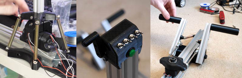
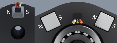
The throw of the joystick is limited by [Tom]’s legs and chair, with only 12° of travel in either axis, which is too small to allow for high resolution with a potentiometer. Instead, he used hall effect sensors and a square magnet for each axis, which gives good resolution over a small throw angle. The pivot that couples the two rudder pedals also makes use of a hall effect sensor, but needs more travel. To increase the size of the magnetic field, [Tom] mounted two magnets on either side of the sensor with their poles aligned. To center the rudder pedals and joystick, a couple of long tension springs were added.
A normal potentiometer was used in the throttle lever, and [Tom] also added a number of additional toggle switches and buttons for custom functions. The frame of the system is built with T-slot extrusions, so components can quickly moved to fit a specific user, and adjust the preload on the centering springs. All the electronic components are wired to an Arduino Micro, and thanks to a joystick library, the code is very simple.
At a total build cost of £212/$275 it’s certainly not what anyone would call cheap, but it’s less than what you’d pay for a commercial offering. All the design files and build details are linked in the second video if you want to build your own.
The flight sim controller builds are coming in thick and fast with the release of the latest MS Flight Simulator. With 3D printing you can augment an Xbox controller with a joystick and throttle, or just use tape and a few electronic components turn a desk drawer into a flight yoke.


total build cost £212, not £121
Fixed, thanks
On cost, though: I never know how to price out stepper motors or aluminum extrusion. Do you attribute the cost to the first project that uses it, or the next one, or the next one…? When he gets tired of playing flight sims, he can just unscrew the extrusions, pitch the plastic parts, and he’s on to the next thing.
It only gets expensive when your projects become permanent.
I’ve always wanted a setup like this to fly with
more so with FPV!!
anyone know where I can get data on the JR et al “buddy trainer” protocol?
This might interest you then. The guys at Flite Test made a sim-style control rig for their FPV planes.
https://www.youtube.com/watch?v=r43zuFWtdaI
landings would be a bitch
this is why I prefer a monitor on a stand rather than goggles, you can look up!
by now somebody must have figured out the “trainer mode” cable thingo protocol
then we could just plug a rig like this into our transmitters
Its just plain old combined pulse pause modulation (cppm) every cheap arduino is able to produce it and there are a lot of libraries and plenty of example code writen for that.
This is one of the few DIY projects I’ve seen on youtube that made me think: 1. I could actually make this, and 2. I might actually want to make this.
Very clean, well designed and executed. Well done!
there are two problems with this hall sensor config. first these sensors unusually have around a volt of dead space at either end. so that clips a lot of res off at either end when you feed the signal into an adc (not as much as with a pot though). the other is you usually have to characterise it. it wont be linear but you can correct it with a look up table fairly easily. but you do need a way to sweep through all angles at regular intervals (stepper motor works) to find it. there are senors with a dsp built in so you can characterize it, program the sensor, and once programmed behaves much like a true pot without needing an intermediate microcontroller.
you can come up with mostly linear magnet configurations but they can be rather finnicky to reproduce accurately. simplest config ive come up with is a roating armature rotating 2 magnets around the sensor with the hall plate as close to the axis as possible. the magnets are oriented north to south so as to create the straightest possible b-fields through the sensor and the value read is proportional to the sine of the angle. gives you about 180 degrees theoretical range but in practice its more like 150-160 practical range depending on sensor. useful in some but not all applications.
A lot of this you can tweak in Flight Sim. You can adjust the dead space and the ramp curve.
If your Hall sensors hit the electrical rails before you get to the physical stops (the “dead zones” at both ends of travel you describe), you’re using too strong a magnet, or too sensitive a sensor. Simple as that. They output a certain number of mV/Gauss (check the datasheet), with the midpoint being 1/2 the applied voltage, and if that exceeds the supply voltage on one side, or 0 on the other, they have nothing more to give, and just stay stuck at their min or max outputs. This is a common problem when using neodymium magnets with Hall sensors. Switch to ceramics and you’ll have less problem with this.
As for linearity, the sensors themselves are pretty linear, but only when they’re in a linear magnetic gradient, which is what Tom has designed into his mechanisms. The ideal way is the way he did it with the rudder sensors, where the sensor is between the N end of one magnet and the S end of another.
might be specific to the sensor too. the ones im using puts out a signal between 1 and 4 volts. the adc expects 0 to 5. so you lose some resolution. you could do away with this with a double ended adc and some voltage references.
sensors are also linear to field strength. but field strength is non linear with distance or angle. depending on your b-field geometry you could get a non linear response. that said there are geometries that are mostly linear. magnet selection is also very important to linearity.
I was going by the datasheet for the Honeywell sensor Tom used: https://sensing.honeywell.com/honeywell-sensing-ss39et-ss49e-ss59et-product-sheet-005850-3-en.pdf, which goes all the way to 0 and to the supply voltage.
Also, your “2 magnets rotating around the sensor” arrangement produces a sine or cosine response (depending on the orientation of the sensor), which is good if you want the sensitivity to drop off near the +/-90 degree points, with the maximum sensitivity at the center. Which by the way is a good way of making a 360degree sensor, by using two Hall devices oriented 90 degrees from each other, then dividing sine/cosine and running that through an arctangent table.
“The flight sim controller builds are coming in thick and fast with the release”
I’m building one also out of extruded rail – I imagine that every 3rd HaD reader is building one .
Great design on the rudder pedals, I hadn’t thought of integrating them into the extrusion that way – a design I’ll definitely be borrowing :-)
Hall effect sensors are great, in that they never wear out or get noisy like potentiometers do. Another application where pots are a bad idea is in sensing the tape tension in a magnetic tape drive. I used to work on Cipher 9-track tape drives, and they used a spring-tensioned roller on a pivoting arm to sense this. On the other side of the bearing for this arm was a variable capacitor, made from two parallel fixed metal plates with a plastic plate that slid between them as the arm moved. Since the plastic had a much higher dielectric constant than air (about 5x), there is a large change in capacitance as the plastic displaces air in the gap. I don’t remember exactly how they measured the capacitance, but these days any microcontroller digital I/O pin set to high-Z input could do it, just as capacitive touch sensors are measured. The really great thing about using variable capacitance is that you can shape the curve by literally shaping either the plates or the plastic insulator.
This is great engineering. I’ve been looking for a realistic flight control for glider pilot simulation and no one has them. You could mass produce these with a little spit and polish and sell online.