Machinists have a lot of neat shop tricks, but one especially interesting one is shrink-fitting tools. Shrink-fitting achieves an interference fit between tool and holder by creating a temperature difference between the two before assembly. Once everything returns to temperature, the two parts may as well be welded together.
The easiest way to shrink-fit machine tooling is with induction heating, and commercial rigs exist for doing the job. But [Roetz 4.0] decided to build his own shrink-fitting heater, and the results are pretty impressive. The induction heater itself is very simple — a 48 volt, 20 amp power supply, an off-the-shelf zero-voltage switching (ZVS) driver, and a heavy copper coil. When the coil is powered up, any metal within is quickly and evenly heated by virtue of the strong magnetic flux in the coil.
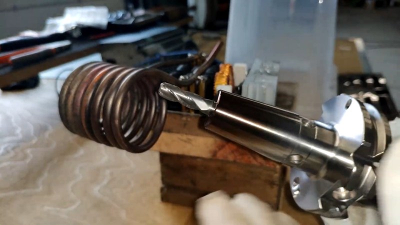
To use the shrinker, [Roetz 4.0] starts with a scrupulously clean tool holder, bored slightly undersized for the desired tool. Inside the coil, the steel tool holder quickly heats to a lovely deep brown color, meaning it has gotten up to the requisite 250-300°C. The tool is quickly dropped into the now-expanded bore, which quickly shrinks back around it. The advantage of this method over a collet or a chuck is clear in the video below: practically zero runout, and the tool is easily released after another run through the heater.
You say you’ve got no need for shrink-fitting tools? How about stuck bolts? Induction heaters work great there too.


DIY induction heater. Step 1) Buy an induction heater…
It you want to build your own: https://www.youtube.com/watch?v=hFJeIt_JcEc
But the reality is that a 1000W ZVS from China will be cheaper than you can build yourself. But building your own lets you understand what is going on.
DIY ones are likely more robust, too. I’ve gotten a couple ZVS’s from a couple of sources, and none has lasted more than half an hour before blowing out the switching fets.
If you plug a cheap module in and run it at maximum power, it will melt. Even if you run it at half the rated maximum power it will melt eventually. And exactly the same will happen if you build your own, but you would spent a lot more time trying to work which bits get hot and will melt unless you apply enough external cooling. Even if a 1000W ZVS module was 94.5% efficient, that is still 55 watts of heat that needs to be continuously removed from the circuit to stop it from melting.
And that is before you get to the work coil, there are a few reason why it is a pipe :)
If you buy cheap chinese stuff like this, it’s more of a kit with a vague suggestion of how it should be put together.
I’ve bought a few of those (extremely cheap) aluminium brick power supplies, and in some of them they’ve placed the power transistors directly to the aluminium (no thermal paste), or not even flat, so only a corner touches the outside casing.
Once even the thermal paste was smeared over the transistor after assembly.
I always take apart these power supplies for an inspection. Check solder connections, remove solder balls, debur transistor mounting holes and mount them properly with thermal paste.
Same with a lathe I bought. Look at it closely, and improve some weak points immediately instead of letting them fail. One of the weakest points was the nuts of the cross carriage. It was some stamped metal, which would have eaten away the circular T-slot in the cast iron over time if not addressed. I milled some bent T-nuts on a rotary table that fit the circular T-slot nicely.
It’s basically the choice between buying a EUR2000 lathe and spend a few days to improve it, or buy a lathe of the same size, but 4 times it’s price.
The price of the Chinese ZVS PCB’s is less than the sum of it’s parts, so just for that they’re worth buying. But even if the MOSfets seem to have a decent heatsink I would not trust the transistors are mounted properly, just as with the power supplies above. These circuits have the bare minimum components to get it to “work” and are in need of some extra protection circuitry. The simplest would be to monitor the temperature of the heatsinks (after mounting the transistors properly). Maybe it’s useful to monitor, or improve on the gate drive for the MOSfets.
A common failure mode of these is to run the circuit at too low a voltage. They do oscillate, but then they do not have enough drive to switch the gates of the MOSfets properly, which results too much heat dissipation in the MOSfets. You can clearly see this in the ElectroBoom video in the link posted by “Truth” above. You can clearly see the “slow rise time” @12:17, but more importantly, the the stair case step at around 4V when the gate is charged (Miller effect). During the whole time of this step, the MOSfet is conducting only partially, which results in high power dissipation. The gate voltage should be a (nearly) straight line from 0V to above 7V (Preferably up to 15V, which lowers Rds even more)
@paulvdh I agree and the other typical reason for the Power MOSFET to pop is not enough cooling, their maximum current rating is usually ~30-40% less at 100°C (212°F) compared to 25°C (77°F). So if the temperature of the Power MOSFET is increasing their maximum continuous current rating is dropping, eventually you need to replace them. The cheap Chinese ZVS is just a module, not a fully finished product, external cooling is needed.
If you want a 3kW or 10kW inductive heating coil, right now, you can probably build one cheaper than you can buy it. ( http://inductionheatertutorial.com – lots of useful information ). But make sure that you build a few tiny low power ones first to learn your mistakes on a cheap circuit. And always test out ideas for your high power device using cheaper lower power ones, so that mistakes are less costly. Once you start bumping up the power there is a jump in price.
Video needs to be marked NSFW, interesting ‘tools’
The most amazing part of this project is why it has taken so long :)
An “official” shrink fit station costs around EUR10000, while such a ZVS circuit costs less then EUR100, and a 50V power supply with enough power to drive it is also in the range of a few hundred EUR. Together this makes it into a very attractive project to DIY.
I would have built such a thing myself if I had a CNC machine for which it was suited.
The project as above looks like a first test and some upgrades seem logical.
First of course some frame, so you do not have to hold the toolholders in gloves, but more importantly for reliably and repeatability of positioning.
I’m not sure about temperature measurement, It seems more logical to simply use a timer for the heating, maybe combine it with a lookup table for different tool holder sizes, and output power measurement of the power supply.
Further, I guess that uniform cooling of the toolholder may improve concentricity. So putting the toolholder vertical while cooling and a screen against moving air seems appropriate.
Another thing to be aware of is the ZVS circuit itself. These are not complete ciruits, but just a building block, and they need additional protection circuitry against faults to work reliably. They also need a bit of tinkering. The connection to the inductor coil is often also a weak point, as you can see @0:55 in the video.
I’m not sure about the price of the toolholders, but I think this is reasonable, because they are so simple. Just a hole on one side and a taper on the other, and the price of the shrinking tool is the major hurdle in preventing wide spread use of these toolholders.
Oops, small addition.
First the price of the induction heater. John Saunders goes to the Maritool site, which shows a price of USD3480 @03:56 into: youtube / watch?v=IENEZwi5qPw
Wich is significantly less than I first thought, but still well worth to DIY.
Then, apparently it is possible to heat the holder quick enough with pliers and a blowtorch to create a steep enough temperature gradient to remove the tool:
youtube / watch?v=mygtW1c30u8
His timing can be improved, but I applaud him for success on his first attempt, and it also shows that timing is less critical then I thought. No need to get medieval.
I am really excited to see something like this for makers- I worship shrink fit tooling.
I used a Haimer Power Clamp Comfort NG shrink fitter for this in an Aerospace shop for almost all of our tools, cooled sleeves with liquid nitrogen too to quickly set the tool in holder.
Shrink fit is amazing once you get used to it- and there are even machines like stuff from Kern that has jig grinding function on shrunk fit tooling- the machine will actually regrind your tool in place in the holder for ultimate concentricity.
Seeing someone figure out how to DIY this just made me really happy!
One big tip- NEVER shrink fit HSS tooling- only carbide. It only works with carbide because it has a largely different thermal coefficient of expansion from steels used to make the holders, if you put steel shanks in, they will just expand at the same rate as the holder- and be stuck forever.
> a heavy copper coil
It is not a heavy coil, it is a lightweight hollow copper pipe. At the frequencies used in a typical 1000W ZFS (~40 KHz) the current in the copper, due to the skin effect, is limited to a depth of 0.326 mm. So having a solid copper coil is a waste of copper, which costs money. And having a pipe, allows you to flow water through it to keep the coil cool.
Bloggers gonna blog, and damn exactitude! It´s all for the glory of the click, and the pennies from the sponsors.
Stuck bolt? Just weld a nut on top. Usually, the heat will crack it loose internally.