Oregon State University must be a pretty good place to go to school if you want to hack on robots. Their robotics club, which looks active and impressive, has a multi-part video series on how to solder surface mount components that is worth watching. [Anthony] is the team lead for their Mars Rover team and he does the job with some pretty standard-looking tools.
The soldering station in use is a sub-$100 Aoyue with both a regular iron and hot air. There’s also a cheap USB microscope that looks like it has a screen, but is covered in blue tape to hold it to an optical microscope. So no exotic tools that you’d need a university affiliation to match.
We agree with [Anthony’s] order of parts. He does components that only have bottom pads first. Then he does the remaining difficult multi-lead components followed by the passives. However, for learning, it would probably be best to get used to soldering some easy components first.
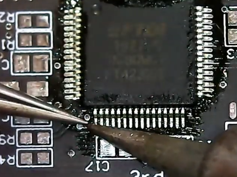
He uses hot air to do the components with bottom-only pads. This is a great way to do it, although we’ve sometimes used nearby pads to inject heat under a part when we didn’t have hot air handy or were too lazy to use it. [Anthony’s] method is to tin the pads and then remove most of it with solder wick. He uses some extra solder to the wick to prime it, although we often use flux for the same reason. He uses the hot air gun but not solder paste, so you don’t have to worry about storing paste to use these techniques.
Doing these parts first makes it easier to control the hot air flow since you don’t have to worry about dislodging other nearby parts you haven’t placed yet. He doesn’t use hot air for the other components that have exposed leads.
Even if you’ve done a lot of SMD soldering, you can always pick up new tips and tricks. There’s lots of flux, of course, and careful alignment before you secure the component down. We know the feeling of leaving a bad solder joint long enough to go secure the other pads and then cleaning it up at the end.
We figure [Anthony] might do well at our annual SMD Challenge although we admit using our tools is what makes it a challenge. Of course, the big trick isn’t always building something new with surface mount components. It is repairing them.


What I’d like some tips on is how to carefully and non-destructively pull up the double decker USB3 ports on the Raspberry Pi 4B without pulling up any pads. Especially those ground pins never never NEVER want to desolder. I’ve tried a 45w desoldering iron, my regular iron turned up varying amounts all the way to 480C, and I’ve added solder, removed solder, added flux, removed tons of inevitable burnt resin, and the only thing that seems to work is cutting it to pieces and poking out the left over leads with a small bit of copper wire while heating those pins until the board is too hot to touch with my hands. Very frustrating. I have had to remove a couple of those and I had to then go back and solder some bodges to the traces after losing pads. So frustrating. It takes hours, and the bodges require a microscope. Ugh.
Desolder the shell pins with desoldering needles first, then heat up all the data pins at once with a huge solder blob and pull the connector out.
The shell pins aren’t a problem. The desoldering iron takes care of them just fine. The problem is the two ground pins in the middle and upper left (or lower right depending on perspective) pins next to the data pins. The ground plane inside the board layers spreads heat too quickly to heat up within a reasonable amount of time.
makes sense. Extra soldering iron touching these pins specifically? Or, even better, board preheating to 100C?
I’ve tried two soldering irons, but holding two irons and pulling on a through hole part at the same time is basically impossible. My main observation is that it heats up quicker, but as soon as I pull one away to yank on the part, it cools back down. I’m not trying to be obstinate. It’s just I’ve already tried that.
Oh, and preheating isn’t something I’m set up for. That might do it, but it requires a lot. No?
Oh I don’t think you’re trying to be obstinate, don’t worry, just that I go through the things I’d do and see if you’ve considered them, which I unfortunately cannot know ahead.
For preheating, usually an IR table is used professionally. However, you can also probably just use a hairdryer on the highest setting and let it blow on the board until it heats up to the same temperature as the fan exhaust – it is certainly going to help in some capacity. Also, if you are using two irons at the same time and *need* two hands for these, try putting the board upside down and attaching some sort of significant weight to the port so that the gravity pulls it. Even “tie long piece of wire to the port hardware and then tie that wire to the foot” will help. This of course assumes that the board is fastened to your table in i.e. a vise – and fastening your PCB is something you should definitely do.
Oh, and don’t forget flux.
Thank you, you’re very understanding. I’ll try preheating next time I run into this problem. I’ve been needing a vice for a while. I gave my last one to the local maker space, so I just need a new small one for my office workbench.
I have an uncle that uses an old electric frying pan for moderate to high heating of things, mostly to softening epoxy, or thread and bearing lockers and up to heating press on bearings. I don’t know if it goes low enough or is accurate enough for this but maybe?…
Paint stripper guns from the hardware store are cheap and effective preheaters. In fact, on the highest settings they can reflow a whole board. Just be careful, there is no indication of how dangerous the hot air is until something is on fire, like your hair.
Let me know how it goes! I’ll be getting notifications for these comments, but also, am on Hackaday.io as Arsenijs (CRImier). Also, good on you for helping a local makerspace, it is a noble thing to do! Still, definitely get a vice, it is an invaluable tool.
Otherwise, you might just have to impro-vice.
use low melt solder (indium alloy) on the pins and tabs to get the melting point of the lead free solder down lower – preheat the board then use hot air to remove the ports…
Here’s some basics to getting heat into a high thermal mass part in case you are missing anything,
ROHS is not your friend. When I did mods to mixed leaded/ROHS board the first thing I always did was what I called “contaminated” the lead-free with leaded solder. Once molten 63/37 solder is touched to lead-free, the melting point at that point drops fast. Having liquid leaded solder is the key, don’t expect the ROHS stuff to melt first, put your solder tip to the joint, and unlike assembling, add solder to the tip at the joint.
(Note: MrX below rightly suggests “low melt solder (indium alloy)” which works the same way as 63/37 but much much better because it lowers the melting point WAY down. Works great if you find the stuff, BUT you have to be careful of contaminating surrounding solder joints. BTW, I found out the hard way it is just as hot as regular solder when you heat it with your solder iron, let it cool before touching!!!!!!)
Liquid solder is your heat conductor, the more area of the target AND the iron tip is covered with the solder bridge, the higher the heat transfer.
If you are touching the solder and it is not melted, the board won’t burn before the solder melts, so you have an indicator of when you are going too far. Give it time to get the heat in, the solder tip is already way above the melting point, so all you have to do is get the heat to transfer, which takes a finite amount of time.
This freaks out the quality people, so don’t do it in a production environment (or at least don’t get caught), but I usually remove the bulk of the solder by heating it to melting and bang it on the ESD pad benchtop. I have to do that all the time as my current project requires I remove small 30A relays from my GFCI protos when I abuse them in testing.
Looks to be a useful ewsote. Their YouTube channel book marked.
Everyone could spend a few days or months learning from Louis Rossmann if you haven’t been to his YouTube channel yet. Also, current time stamp for the video link references his Right to Repair battle (he has video(s) of him testifying for Right to Repair) and also his database of repair tips and tricks videos/resources that he and others are compiling. FYI
https://youtu.be/H9OUZzvlc6w?t=680
Plan on spending a few days if you are new to his channel. :)
Louis Rossmann is great. He mostly deals with surface mount, which really isn’t a problem. It all heats up quickly. It’s inner ground plane connected through hole that drives me insane.
When doing wave touchup on aircraft PCB in the through hole days, I used to watch them using 3 soldering irons (2 people) on a lead that went through several ground plains.
Holy crap man!! Get the proper tip for soldering FQFP, TQFP!!! Total wrong tip for the job.
When you’re doing it on the cheap, you make do with what you got.
Although it is a balancing act, so it doesn’t end up with every problem looking like nails because you only got a hammer.
How do you heat the hammer up to a high enough temperature to melt solder, without a blowtorch?
I don’t have these problems, but your comment is basically saying “stop being stupid” without any suggestions for what being smart is. What’s the proper tip?
I recall listening to a talk by Jonathan Hurst, a professor of robotics at OSU – he mentioned that some of the Carnegie Melon robotics field graduates ended up at OSU to do research, and created the Robotics dept there. As these fields slowly distribute, depending on how strong the field is, I think we’ll end up seeing robotics departments all across the country. It’ll take a couple of generations though.
I’m really surprised to see it being done that way. I soldered SMD chips only a couple of times, and used a different technique: I put flux in both the board contacts and the bottom part of the chip pins, and then passed in each one separately the soldering iron with a little bit of solder. That covered each part with a little bit of solder tin, but eliminated the need of using copper tape to remove any excess. Then, I placed the chip in its final place and applied heat with a dry soldering iron, thus making the solder tin already in the pins and board to melt and fusion. Finally, a revision with the multimeter to ensure that every pin is correctly soldered, and the result was always great. Only once I had a faulty pin (detected with the multimeter), but was fixed with just a little bit of heat with the soldering iron.
But I’m not an expert, so probably my method has its drawbacks…
Not had a go at a pi4 yet, but if you don’t care about the port trim it down so its got as little thermal mass as possible while being easy to grip in your pliers, then drag a massive solder blob onto the back – it will quickly melt all the solder connections so you can pull the husk out in one.
Its always worked for me on protecting the pads and other components – that big preheated solder blob very quickly melts the existing joins for removal and often just falls off itself when cool.
Wow, I would have made these videos more professional if I’d known anyone from outside the club was going to see these. Come check out our club if you’re ever on campus! We do lots of really cool work!