Some may ask why you’d want to program a Cortex-M microcontroller like the STM32 series using nothing but the ARM toolchain and the ST Microelectronics-provided datasheet and reference manual. If your first response to that question wasn’t a panicked dive towards the nearest emergency exit, then it might be that that question has piqued your interest. Why, indeed?
Definitely, one could use any of the existing frameworks to program an STM32 MCU, whether the ST HAL framework, plain CMSIS, or even something more Arduino-flavored. Yet where is the fun in that, when at the end of the day one is still fully dependent on that framework’s documentation and its developers? More succinctly, if the contents of the STM32 reference manuals still look like so much gibberish, does one really understand the platform?
Let’s take a look at how bare-metal STM32 programming works, and make the most basic example run, shall we?
Like a PC, only different
Fundamentally, there is little difference between a microcontroller and a full-blown Intel or AMD-based computer. You still got at least one CPU core which is initialized once external power has stabilized, at which point start-up firmware is read from a fixed location. On your desktop, this is the BIOS. In the case of an MCU this is the code stored starting at a specific offset in the (usually) integrated read-only memory (ROM). Whatever happens next is up to this code.
Generally, in this start-up code one wants to do the essentials, such as setting up the interrupt vector table and the basic contents of specific registers. Initializing the stack pointer (SP) is essential, as well as copying certain parts of the ROM into RAM and initializing a number of registers. Ultimately the main function is called, akin to when the operating system of a PC is started after the BIOS has finished setting up the environment.
The Pushy example
Probably the most basic useful example would be what I affectionately call ‘Pushy‘ in my Nodate STM32 framework. It’s more basic than the traditional ‘Blinky’ example, as it only uses the Reset & Clock Control (RCC) registers and basic GPIO peripheral. All it does is read the input register of the GPIO pin and adjust an output depending on the input value, but that still gives one the power to turn a LED on or off at will:
[gist https://gist.github.com/MayaPosch/d4b71ae6ba86f9e5e036d00dd8c9bacf /]
Here we can see the two most visible elements: first is the main() function that gets called, the second is the included GPIO module. This contains a static C++ class which gets called to write to the GPIO output, with connected LED, as well as read from another input that has a button connected to it. We can also see that the so-called ‘Blue Pill’ (STM32F103C8) has its pins defined, but the example has a few more presets we can change by uncommenting the appropriate lines.
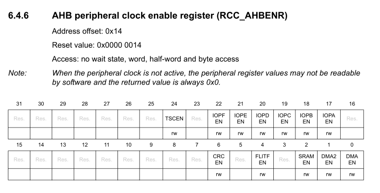
So where do the RCC registers come into play here? As their name suggests, they control the clock domains within the MCU, essentially acting as on/off switches for parts of the MCU. If we look at for example the RCC_AHBENR register description in the STM32F0xx Reference Manual (section 6.4), we can see a bit there that’s labelled IOPAEN (Input/Output Port A ENable), which toggles the clock for the GPIO A peripheral. The same is true for the other GPIO peripherals.
As listed in the above graphic, AHBENR means the enable register for the AHB, which is one of the buses inside the MCU to which the processor core, SRAM, ROM and peripherals are connected:
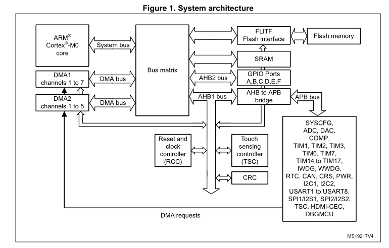
The AHB (Advanced High-performance Bus) along with the APB (Advanced Peripheral Bus) are covered by the Arm AMBA specification. Generally, the AHB is the fastest bus, connecting the processor core with SRAM, ROM and high-speed peripherals. Slower peripherals are placed on the slower APB, with an AHB-to-APB bridge allowing for communication.
Time to assemble
As mentioned earlier, the first code to run is the start-up code. For the STM32F042x6 MCU, a generic start-up program in Thumb assembler can be seen here. This is the generic ASM as provided by ST (e.g. for STM32F0xx) along with the CMSIS device package. It initializes the MCU and calls the SystemInit() function in the low-level CMSIS C code, e.g. for STM32F0xx.
This SystemInit() function resets the system clock registers to the desired reset state: using the internal HSI oscillator, at default speed. After libc setup routines (here Newlib, a C/C++ support library), it finally starts the main() function with:
bl main
This instruction means ‘Branch with Link‘, causing the execution to jump to the specified label, essentially. At this point we’re firmly in our ‘Pushy’ example’s main(). It’s now all down to the GPIO class to pull things together.
GPIO
The first class method we call is GPIO::set_output() to set a certain pin as an output with enabled pull-up resistor. This is also where we encounter our first differences between the STM32 families, as the older Cortex-M3-based F1 family has very different GPIO peripherals from its newer F0, F4 and F7 siblings. This means that for the STM32F1xx we have to wrangle multiple options per pin into a single register:
[gist https://gist.github.com/MayaPosch/2272560bbd38f4f882e3d80cfbd21c20 /]
But for the other mentioned families we have a different register for each option (mode, speed, pull-up/down, type):
[gist https://gist.github.com/MayaPosch/1a1c93c6113a28d8cda40f2799431ce7 /]
Setting an option in a register is done using bitwise operations to set the target bits through bitmask manipulation. The register name is usually fairly descriptive, with for example PUPDR meaning Pull-Up Pull-Down Register.
Which style one prefers is mostly in the eye of the beholder. In the case of setting a pin as input, however, I much prefer the newer GPIO peripheral style, with the following nice, compact code instead of the STM32F1xx convoluted horror show:
[gist https://gist.github.com/MayaPosch/8b896e7f6bcaa74a407251661339fce6 /]
To read from an input pin, we reference the Input Data Register (GPIO_IDR) for that GPIO bank:
[gist https://gist.github.com/MayaPosch/a84fb356eb096e3c435a50c0ec494d4f /]
Similarly, we use the Output Data Register (ODR) when we write to a pin:
[gist https://gist.github.com/MayaPosch/2e4d761821350867cb05016f129f86c7 /]
Finally, the instance in the above code snippets is a reference to an entry in an std::vector which was created statically upon start-up. It registers properties for each peripheral:
[gist https://gist.github.com/MayaPosch/5128d064d2048d353180dc319a918810 /]
If a peripheral exists (i.e. listed in the CMSIS header for that MCU, e.g. STM32F042), an entry is created in a GPIO_instance struct pointing to its memory-mapped registers (‘regs‘). These instances can then be referenced along with any meta information in them, such as whether they have been activated yet:
[gist https://gist.github.com/MayaPosch/7139aa853733d12d5fdbb5c7e9ec6419 /]
The advantage of this is – as we saw earlier – that the same code can then be used, no matter which peripheral we’re addressing, as they are all identical in terms of register layout.
RCC
The RCC class also tracks whether a peripheral exists using the same CMSIS preprocessor defines to prevent any surprises. After this, enabling a peripheral’s clock is quite easy:
[gist https://gist.github.com/MayaPosch/9443988784d8e31ce2c00a900a3be7a6 /]
In addition to toggling the relevant bit position (ph.enable), we also perform reference counting, just so that we don’t accidentally disable a peripheral when another part of the code is still using it.
Running the example
After working through the above material, we should have some idea of how the ‘Pushy’ example works on a fundamental level. We can now build and run it. For this we need, as mentioned, the ARM toolchain and Nodate framework installed. The former can be obtained via one’s favorite package manager (package: arm-none-eabi-gcc) or Arm website. The Nodate framework is obtained via Github, after which the location of Nodate’s root folder has to be specified in a global NODATE_HOME system variable.
After this has been taken care of, navigate to the Nodate folder, and into the examples/stm32/pushy folder. Here, open the Makefile and pick any of the board presets (currently Blue Pill, Nucleo-F042K6, STM32F4-Discovery or Nucleo-746ZG). Next, open src/pushy.cpp and ensure the appropriate lines for the target board are uncommented.
Next, in the folder with the Makefile, build with make. With the target board connected via ST-Link, ensure OpenOCD is installed and flash with make flash. This should write the firmware image to the board.
With a button connected to the specified pin and Vdd, pushing this button will make a LED light up on the board. This demonstrates the basic use of an STM32 GPIO peripheral, and you’re already one step beyond “blinky”.
Hopefully this showed how bare-metal STM32 development is rather straightforward. Please stay tuned for more advanced topics as we push further into this topic.


i did not want to use C language or arduino libraries or bloated IDEs for stm32, and collected the resources i needed here http://galexander.org/stm32
Nice introduction – you might also want to briefly mention how to install the ARM GNU toolchain.
It might also help to explain how CPU and peripheral registers are usually accessed as pointers to specific memory locations, and how all of those structs like “GPIO_instance” relate to those register addresses and bitfields.
It sort of feels like this post jumped right into using a HAL, but maybe I missed an earlier post in this series.
(Sorry, most of those things are mentioned, I just didn’t skim closely enough to catch them. Nice article!)
For a project for my job, I had to use the toolchain directly, as you say here, and the first thing I did was to build a very simple event/message queue. It greatly simplifies working with interrupts.
FreddieChopin did taught stuff like 10 years ago. It’s worth looking over his tutorials because he doesn’t play around with balls but focuses on raw teaching.
I do all my driver bare metal but in C++, faster, smaller, and it give you a better understanding of the chip and peripheral. I build a complete graphic GUI system for STMF7 and completely bare-metal… not a single inclusion other than STM32f746.h, in a few week I will even release a GRBL version using my GUI on a stm32f7-discovery…. can’t wait to see if people will like it. If someone say C++ if not efficient with size code, they should read the IAR document about what can be use or not in embedded C++.
Are you planning to public the code under some opensource license?
Yes.
It will be on
https://github.com/aroyer-qc
when ready!!
Excellent, I felt like I was the only one doing this e.g. a compile-time generated set of dynamic interrupt handlers/hooks: https://gist.github.com/timblakely/a1c9b1795043ebfc3e5023825433dc9b . Now if only WG21 would get their act together and make std::start_lifetime_as (neé std::bless) a thing…
Anywhere we can follow the details?
How does doing bare metal in C++ “give you a better understanding of the chip and peripheral”?
Nice article! (reminded me of this https://github.com/dwelch67/raspberrypi)
I’m not in the mood to read the whole article today, but it brings up memories of:
http://pandafruits.com/stm32_primer/stm32_primer_hardware.php
It was the most informative article I could find when I started with STM32.
It also handles the bare bones stuff from the ground up, from writing your own linker script, to handling offsets for IO register bans and the first steps of connecting to GDB for debugging.
If you are interested in bare-metal ARM programming, this project may interest you : https://libtungsten.io/ . It’s for the ATSAM4 family, not the STM32, but it’s a similar Cortex-M4 MCU from Atmel/Microchip and the principles are the same.
It’s basically an HAL which aims at being well-documented, with well-commented code, in order to be read, understood and customized. It started as an exercise to learn more about the low-level stuff (just like this article), then evolved into a (mostly) stable library that covers most of the chip’s capabilities. It powers all my embedded projects.
Documentation is still missing a few things but there is already plenty to read for those who would be interested (there are not a lot of examples yet though). A GDB tutorial covers how to use this tool to inspect the behavior of your program directly in the chip : https://libtungsten.io/tutorials/gdb.
(Disclaimer : I’m the author of this project, in case that wasn’t already clear)
Isn’t HAL pretty much opposite of bare metal programming? And I don’t really get, how to abstract out features unique to particular chip/family. Like that DMA thing, STM32F1xx HW can loop in circles – scanning ADC chans on its own and even placing results into desired place. Good luck to persuade e.g. AtMega to do something like this. Their HW isn’t as cool – it got no DMA to begin with. At most I can imagine IRQ + irq handler emulating this, but it still needs device specific setup and irq handler and nowhere as cool as mentioned combo STM can do, where whole heavy lifting goes in hardware without software intervention at all – which is whole point of DMA.
Yeah, but the HAL code itself is the beauty, as it is, itself, bare metal code.
“Isn’t HAL pretty much opposite of bare metal programming?”
No. In bare metal programming you still have libraries and code reuse, so the HAL is just an interface to library code that can be shared across different systems. There is no runtime layer, that’s the difference from an OS HAL.
With CMSIS you just get a compatible interface that libraries implement, mostly with macros. So there isn’t an OS, but there is still a consistent interface defined by ARM that the different vendors implement. For example, the TI driver libraries normally implement both the TI “driverlib” interface, and also the CMSIS interface. So most of the code above would be easy to port.
Well Maya, minds meet!
After recently writing an article on Baremetal programming on the tinyAVR-0 (https://www.omzlo.com/articles/baremetal-programming-on-the-tinyavr-0-micro-controllers) which got featured on Hackaday recently, I was starting to write a blog entry tentatively titled “Baremetal Programming on the STM32 from scratch”. I’m taking a slightly different angle, diving even deeper, but I’m looking at very similar stuff!
I’m also experimenting with C++ on the STM32L031. My approach here is quite different from you however as I treat peripherals such as GPIOs as objects, e.g.:
“`
// Declare Status_LED as pin 0 on port B
GpioClass Status_LED(GPIOB, 0);
// use
main() {
…
Status_LED.configureAsOutput();
Status_LED.digitalSet(); // Set the pin to high
…
}
“`
This allows me to pass GPIOs (any other peripherals) as parameters to functions for example.
Anyway, good article!
Nice article!
I am a big fan of the STM32 series and for me, bare metal is the only way to go.
I could give lots of reasons, but above all it is more fun.
But I wanted to pass along this entertaining thought from a fellow I collaborate with. We both detest the Arduino environment, and he said, “it is like making love in a fur coat!”. Not the first metaphor I might have thought of, but I think it sums up the situation quite well.
Some of my bare metal exercises are here:
https://github.com/trebisky/stm32f103
Nice article
I am a big fan of the STM32 series and for me, bare metal is the only game in town.
It is all about having the most fun.
I was talking to a collaborator about this. He and I both detest the Arduino environment. He said, “It is like making love in a fur coat!” Not the first metaphor I would have thought of, but very apt I think.
Personally I enjoy STM32F1xx hardware. A very well thought masterpiece. Even simplest F1xx can acquire up to 16 ADC channels in a loop, back that by DMA and keep looping all that entirely in hardware.
Equally pleasant surprises in many other places. Well, some oddities as well, but I’m yet to see better hardware.
Same could be told about Cortex M3 core and surroundings like nvic, etc. Neither overengineered, nor crippled, it feels … like 6502 done right. Really, really right. Using modern approach and techs, where you don’t have to save each and every transistor at expense of crappy hardware “api”.
love the metaphor, I have been porting the bigtreetech touch firmware to various lcd touch screens as well as hacking various stm32 devices including dumping locked chips and reversing the encryption method, for speed and time saving I have a two step method for making a “hello world” for a stm device, I use stmcube generator to select clock speeds /gpio/HALS and export with Makefile option selected, the drop in a platformio.ini with platform = stm32cube as your build environment, and hit compile. stlink/bmp and many other debuggers supported, i can then test unknown pins/hardware and build up a base board bring up for unknown device. the hals give me ability to test the components without having to dig into a register deep in some manual when platformio allows me to jump to the lower level register values in the .h files . the makefiles will build under windows with WSL enabled and arm-gcc installed in the path. this method also allows me to jump HAL’s eg cmsis when try other code sources. I am no expert and do this for fun so this is the method ive found gets me to hello world in a ide with debugger. also works with linux/atom/wine for stmcube. once i get used to a board i skip the cube part and dig into a prior project and rip the needed lines of code out. One tip i will give is use the UART/hard fualt handler when debugging, a example here https://github.com/darkspr1te/mkstft35_V1_open_bootloader/blob/master/Src/stm32f4xx_it.c , along with adding the syscalls.c file and your printf redirection.
I perhaps don’t understand your friends use of the phrase. Maybe it’s me, but that ‘fur coat love’ sounds nice.
But perhaps in the metaphor the lovers are in separate coats?
MIT licensed GNU C STM32F103 project template which does all the things missing here, such as configuring the HSE (High Speed External) clock and peripheral bus clocks for 72MHz.
https://github.com/gnif/STM32F103-BareMetal/
Whoa, cool. I think I did something similar… though I’ve added a bit more fancy macros to make MCUs fun and defines looking more eye-candy and hard to use wrong ways.
I’ve had fun booting STM32F1xx from ground up – by own code. That is – I’ve not used any foreign code at all!!! Not even startup files – absolutely everything happens in my code, my code and my code – so I control it down to last bit. Um, well, and my linker scripts. That eventually grown a bit more advanced, like separate stacks for handlers and background, and stack is below everything else. So on overflow hard fault would happen, even despite lack of MMU, therefore Toyota-style failures would be thwarted in the very beginning of the trouble.
To make it more fun I’ve also bolted all that into classic *nix Make files – and it’s happy with e.g. debian’s stock arm-eabi-none compiler. So it’s quite Linux friendly – and I can use my favorite editor to write STM32 firmware, yay. Yes, go to hell, dear Arduino, your IDE is horrible piece of junk compared to mere Geany, GTK+ lightweight IDE (or advanced programmer’s editor).
First I’ve created some utils to fiddle with “hardware registers” in a bit more convenient way (you have to flip bits and so on, you know, and C on its own isn’t very nice at this part). Then I read datasheet and defined some peripherals in .h file – my own way, not anyhow based on cmsis/stmicro files or something. I’ve coded self startup – in C – that sets up proper C arena in process. Seems C could be cool enough to bootstrap itself – without resorting to assembly at all, yay. Though later I had to code some asm things, otherwise no fast ways to globally enable or disable IRQs.
Over time thing has been improving. Now … I touched DMA powers this way, orchestrating F1 ADC to do SCAN+CONT in cicrcles, sequencing some scan – and then DMA engine also loops in a matched circle, transferring data into some buffer. So at the end of day hardware magically puts these samples into this buffer – and repeats all that on their own. So there is “magic” buffer that somwhow contains “recent” values of plenty of ADC channels. All code have to do is to … access this array and use samples whatever way it wants. Well, can also optionally throw (high proirity) IRQ upon cycle completion, if processing needs sample-accurate timebase.
p.s. code is … debatable. I’m not sure I should release it. I like some things about it. And dislike some things about it. But overall I guess I have a lot of fun custom way.
Looks like your example is “How to write your own GPIO library” instead of writing a code in bare metal.
i.e. If you need to call a function with a dozen lines of code trying to parse what your I/O function is, it is by definition not bare metal.
You should have written directly to a register instead. Set up macro/enum for those bits to make it more readable.
if (pupd == GPIO_PULL_UP) { instance.regs->PUPDR |= (0x1 << pin2);
Instead of doing code like that, define GPIO_PULL_UP as the values that you put in the register directly. The whole point of bare metal is to skip the layers. You are merely replacing someone else's library call with yours.
Well, still, at some point doing JUST “register transfer” gets rather … tricky.
1. It’s unsafe, prone to bugs and easy to get wrong. You can get with it on something of AtTiny size. But if you want slightly larger firmware with more complicated logic, things can get quite bugged – and it could get hard to get idea why. Because long bunch of HW REG xfers is quite hard to grasp “here and now” on its own. Doubly so if you’ve forgot to put comments and sane names.
2. It’s not really well readable. Its possible to add fancy sugar via #defines – but at the end function like macro (that costs you nothing!), or actual function (often optimized to equivalent of macro/define) could end up being way more readable. And less prone to bugs. Eventually at same price and efficiency as other things. E.g. GCC can be very smart about inlining and LTO can do nice magic on firmware size.
3. Function can also check input parameters, rejecting obviously invalid ideas. Efficiency is good. But safety and security also good. So depending on what we want… tradeoffs can vary.
As good example: when I coded DMA transfers, I’ve managed to get slightly confused – to extent I’ve passed DMA address of pointer to … well, proper pointer, address of which had to be put into DMA. Problem is that DMA isn’t going to dereference pointer for me. So I’ve set sail for fail at the very start.
Needless to say, wild DMA doing something unexpected can cause a lot of weird crap. Which is also hard to debug or get idea why it happens at all. But it didn’t! Since I coded thin shim over DMA addresses setup – and it told me basically “you nut, what the hell this address is?!” – at which point problem got caught straight on 1st attempt to use DMA. But I’m pretty sure extra check added some small – but measurable – extra code. It’s possible to e.g. have “debug” and “release” builds though, where too verbose debug and some checks are optimized out. But you’ll have to live with chance firmware going nuts unexpectedly. Not a big prob if you blinking led. But quite an issue if it controls something dangerous or something can blow up due to, say, incorrect MOSFET combination or so.
Maybe “HAL” is not the correct word for it. What I meant, and I think is relevant to the article, is that this library tries to encourage you to look at the code and see how an MCU works at a bare-metal level, and customize it to your needs. This is why the library is directly copied into your project folder, easily accessible and modifiable on a project-by-project basis, and also why the documentation refers directly to the datasheet (mainly in the Hacking section) and displays the code of the module to show how the registers are configured in this particular peripheral. The documentation includes a tutorial which tries to demystify the datasheet and to encourage the user to look into it.
I also agree with you about the unique features of a chip, and I don’t like general purpose HALs for this reason (IMO, it usually end up looking like a “common denominator” by trying to be too universal, or too complicated to use because of all the particularities of all the supported chips). This is the reason this library only support one chip (or more precisely a chip family, with the only differences being the pin mapping table and the Flash/RAM sizes, which are configured in the Makefile).
Sorry, this was meant to be a reply to @something358’s comment above
I’ve got impression in the end some people tend to follow somewhat similar patterns.
Though seems I’ve chosen more of “efficiency” and “chip-specific features” over “portable” or “high level” – but once again, it’s neither binary choice nor set in stone it seems. It even somewhat evolved over time for me. Yet stll i’ve gone for some black magic with macro and C. Because all of that could be pre-computed by compiler at compile time – so it’s good for compact and efficient code. It’s like half of benefit for baremetal to my taste.
Basically, when I write LED2_ON; I’m fairly sure it unfolds to BIT_SET(reg, BIT) that is a macro that generally precomputes into fairly efficient asm. When I do so in more advanced way, I’m far less sure what the resultuing code would be.
I’ve also had rather silly thing. Abstracting ADC… well, okay, doable to some extent, modulo unique features. Abstracting DMA… fine, it shares same ideas in various places. Abstracting out orchestrated ADC+DMA interaction that is specific to STM32 and very particular setup… that’s where my imagination failed. I don’t have idea how to make this portable. At most I can imagine others can emulate that by e.g. ADC IRQ + custom handler, but it’s not really 100/% equivalent (it cares if IRQs are on; code takes time on bus).
Looks like there’s quite a few who are programming their STM32s in C++, nice.
In the end for GPIOs I settled for a template metaprogramming approach, have a look here: https://github.com/fedetft/miosix-kernel/blob/master/miosix/arch/cortexM3_stm32/common/interfaces-impl/gpio_impl.h
Also simple to use:
//example.cpp
using button = Gpio;
using led = Gpio;
int main()
{
button::mode(Mode::INPUT);
led::mode(Mode::OUTPUT);
led::low();
while(button::value() == 0) ;
led::high();
for(;;) ;
}
And angle brackets were stripped from the comment… looks like posting template code as comment to an hackaday post isn’t easy…
The code should have looked like this, but with angle brackets instead of parentheses…
using button = Gpio(GPIOA_BASE,0);
using led = Gpio(GPIOA_BASE,1);
Yes indeed, being able to do code formatting here would be a improvement.
What a coincidence! I received today an STM32G431 STM32-NUCLEO card and started to write C header files for registers. I will switch to your nodate git to save me work.
“The first class method we call is GPIO::set_output() to set a certain pin as an output with enabled pull-up resistor.”
Please correct this sentence, you probably intended to write “push-pull” as pull-up(down) resistors are use in input mode.
A great resource for all people getting into stm32 without using the (bloated and overly complex) HAL:
https://vivonomicon.com/
I don’t know the author, but his examples pointed me well into the right direction. This evolved into building my own 10kW solar inverter with mppt directly connected to our 230V/50Hz grid.
I’m afraid I’m not terribly convinced by arguments to the tune of “my Nodate library is more ‘bare metal’ than ST’s HAL or Arduino.” Nice write-up though. (I guess – it’s not really what tools you end up using, it’s how deep you look into how they work…)
About 6 years ago (!) there were some discussions on EEVBlog forums about “Ghetto STM programming”, without needing to download gigabytes worth of compilers, IDE, HALs, STPLib, or etc, and it led to this repository:
https://github.com/WestfW/Minimal-ARM
(It didn’t get a lot of interest, though. Apparently, not a lot of people want to program ARMs in assembly language.)
The goal is mostly to show how bare metal programming is done, using example code with which I am quite familiar.
That just happens to be the code that I wrote.
Beware, if you dare program the STM32F103 I2C peripheral directly, it has some nearly fatal errata which cost me untold hours once when I couldn’t bear bit-banging. Iirc, even one of the two ST provided libraries gets the workarounds wrong. It’s… Not fun. If in a pinch, just bit bang it, it’s probably fast enough.
Nice, and nice write up! I will definitely check this out.
It’s so difficult to navigate the interpipes looking for examples on these kind of things. A lot of it is never shared, old school engineers working on firmware never heard of github either. It can be quite uphill.
Regardless of what template of framework you use, anything moire than a blinky (when you have to set up complec timers, OCC, ADC, DMA, etc…) I really recommend using ST’s own CubeMX tool (if not the IDE, at least the code generator package). It really simplifies the process of getting you started.
What I do now is start with CubeMX and CLion’s CubeMX plugin to kickstart a project. It gets your target “blinking” via OpenOCD in 1 minute. Then I go from there but when I am satisfied with the generated code, I ditch the .ioc (it staysin the git repo anyway for reference if needed) and continue with the project as a fully CMake project.
This is something I have been working on, it samples audio at 72 kHz, using DMA, to detect whether there is a “beep” tone:
https://github.com/istepaniuk/dishwasher-beep-detector
This article might come handy, i have to read it carefully later. I have a Blue Pill laying around, but until now the 1000 pages reference manual scared me a little…
Enjoy Rust at https://me.kxd.dev/2020/10/04/rust-on-px-her0-part-1/
When a micro has a 1000 page reference manual it’s not a micro anymore. It’s a entire system on a chip. And when it needs a HAL to hide the ugly complexity of it and make it accessible to mere mortals. Well it’s no chip for hobbyists.
I;m sure it’s a fine micro to use if that’s all you do 10hrs a day at work. But it looks like a real PITA to mess with otherwise.
I second this! Have read and worked through quite a few of the articles/tutorials on this site. It gave me great insight in how to use the startup assembly, write a load file and get from reset to main.
This was meant as a reply to ‘Paul Simon’ regarding https://vivonomicon.com/
I prefer eRuby
This is a baremetal demo of DMA on the STM32, that I did https://github.com/spanceac/dma-demo
No library used, not even libc
Seems some ideas tend to converge a bit… though I’ve gone a bit further, not even using ST headers. Looking on all fun ppl have there guess I should probably put my thing on the web.
It has long been very clear that the phrase “bare metal programming” is another way of saying “assembly language programming”; one can get no closer to writing instructions which operate ‘the (semi-)metal’ than with assembly language. The assembly language mnemonics are, after all, one-for-one replacements for the machine’s binary instructions, or binary code.
It is not at all clear as to how (perhaps “why” would be a more accurate word) this exemplary tutorial manages to equate the procedures, abstractions, other languages used, and tools used, with assembly language programming; clarification would be more than welcome and deeply appreciated.
“By understanding a machine-oriented language [i.e., Assembly Language] the programmer will tend to use a much more efficient method; it is much closer to reality.”–Donald Knuth
It’s not bare metal at all. Then again ARM assembly code isn’t all that fun nor is reading through thousands of pages of a ARM data book to figure out what goes where, etc.
But…but…
the title states…
Bare-Metal STM32: From Power-Up To Hello World;
and, in the body of the article, it is stated…
“…Let’s take a look at how bare-metal STM32 programming works…”
So–is this an article on Assembly Language programming…or not? All indications are that it is not.
Thanks Maya, I’ve been looking forward to this post!
That’s perfect! I like the simplicity, no stupid framework to dig through. Thanks!
That chip is clocked at 180Mhz? I still have Frodo emulator running on PalmOS Tungsten T2 (OMAP1510 – 168MHz ARM) and it runs full speed with sound. Emulation is not cycle exact so disk fastloaders do not work but otherwise games just work.
oh, sorry, wrong page, belongs to https://hackaday.com/2020/11/18/c64-runs-on-stm32f429-discovery/
Seems like a lot of overheads. Using of vector and heap for microcontrollers is not good idea. You can use static polimorphous instead.
To access to register you can see the arrivals here
https://m.habr.com/ru/post/459204/
and here
https://m.habr.com/ru/post/459642/
For ports and pins
https://m.habr.com/ru/post/473612/
You should always use the correct tools for the job. There is not *always* a need to go bare metal. I work in the medical industry, and there is some bare metal needed there, but there are also a lot of frameworks that are used.
I learnt so much about actual bare metal programming from a youtube series.
This guy, teaches bare metal programming. From the ground up. For Cortex M series.
For anyone interested check it out, look for Miro Samek on youtube.
OK, I’m hooked ! How do I download, install, configure and use Nodate STM32 framework. Your link points to the GitHub repository, but I can’t find how to install or use it.
? I’d like to use the STM32CubeIDE without its HAL library. Being that the IDE is really just the Eclipse IDE tailored for STM32 development its very easy to use: Open my project, edit any of the files listed and then simply press the green “Go” button to automatically compile, assemble, upload to my MCU and let it run.