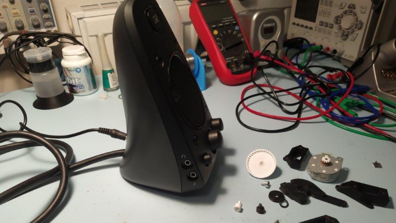
[Haris Andrianakis] likes his Logitech Z623 sound system. He likes it a lot. Which is why he was willing to hack in his own remote volume control rather than just get a new pair of speakers. But he certainly didn’t make things easy on himself. Rather than trying to tap into the electronics, he decided to take the long way around and motorize the volume knob.
The idea seemed simple enough. Just drill a hole through the PCB behind the knob’s potentiometer, attach some kind of extension to the axle, and turn it with a small servo. Modifying the PCB and potentiometer went well enough, but the trouble came when [Haris] actually tried to turn the thing.
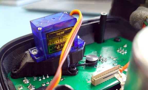
Attaching the servo directly to the axle worked, but it made turning the knob by hand extremely difficult. His next idea was to add a small belt into the mix so there would be some slip in the system. But after designing a 3D printed servo mount and turning custom pulleys on the lathe, it ended up having too much slip, and the knob didn’t always move when the servo turned.
He then swapped out the servo for a small stepper motor. The motor was easy enough to spin when powered down, but didn’t have quite enough torque to turn the knob. He tried with a larger stepper motor that he salvaged from an old printer, but since he could only run it at half the recommended 24 VDC, it too had a tendency to skip steps.
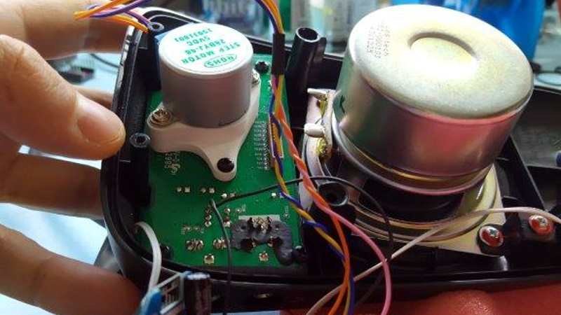 After experimenting with some 3D printed reduction gears, [Haris] finally stumbled upon the 28BYJ-48. This small stepper with an integrated gearbox proved to be the perfect solution, as it had enough muscle to turn the knob while at the same time not restricting its movement when powered down. The rest of the project was relatively easy; with a DRV8825, an ESP8266, and an IR receiver, he’s able to spin the stepper with his TV’s remote. A simple web page running on the ESP8266 even allows him to control volume over the network with his smartphone. Based on similar projects we’ve seen, he could probably add support for HDMI CEC as well.
[Haris] says you shouldn’t follow his example, but we’re not so sure. He kept going when others would have given up, and the engineering and thought that went into each attempt is certainly commendable. Even if he hadn’t ultimately gotten this project working, we’d still say it was a valiant hack worthy of praise.


esp8266 and pwm.
Umm… he’s using an ESP8266. And PWM? I assume you mean using PWM to control the speed of a DC motor? This likely wouldn’t work without going to a closed loop feedback system. The initial torque required to start moving the knob is likely much higher than the torque required to keep it moving. This will result in the volume not adjusting in any sort of linear way. Holding down the volume +/- key would start adjusting the knob at a reasonable speed, but then it would rapidly increase/decrease once it starts moving.
A stepper motor was the best choice in my opinion. This allows him to tap the volume up or dn button and the motor will increment accordingly. Incrementing specific rotation is what stepper motors do. Also, a stepper motor can rotate at the exact prescribed speed, allowing the user to hold down the volume button for larger desired changes to volume, and the volume knob to then rotate smoothly in a way that wont make the user go insane.
Why wouldn’t it be possible to use an LPF and a transistor to simulate analog?
You could definitely use an LPF and transistor to simulate analog. While DC motors can run off pwm, a simulated analog output would make the motor run smoother and quieter. BUT that doesnt solve the issue I was trying to explain. For controlling a volume knob, it is desirable to index prespecified angle increments. Eg: Tap the Vol+ button and the knob rotates 10 degrees. Also, you would like a 2 second button hold to rotate the knob twice as much as if you held the button for one second.
So by the very nature of this application, positional control is a desirable core function. And since open-loop is fine for this application, a stepper motor seems logical. If you just powered a DC motor with PWM or true analog voltage control, you are relying on “motor on time” to get you to the intended angle displacement. This would require lots of playing around and “calibrating” what number of milliseconds of “on time” results in what angle displacement. And its more a pain when you do large changes in volume, as the DC motor will accelerate up to its final speed, making your volume changes start slow, then accelerate. This results in either slow volume changes or the potential to shoot past your intended volume as the motor accelerates. The only way around this would be to use a large, high torque/low rpm DC motor, such as a gear motor. This would ensure the motor doesnt spend much time accelerating and rotates smoothly at the desired speed throughout its “on time” – essentially acting as an open loop controlled motor that uses “on time” to control displacement rather than a stepper motor that is controlled by being fed steps.
TL/DR: This application involves controlling angular position. And that is exactly what stepper motors are designed to do. Also, stepper motors are cheap and available in every size. Sure you could do it tons of different ways, but why not use a drive system ideal for controlling angular position when there don’t seem to be any real downsides to it?
my Technics GT650 from the late 80’s has a motorized volume knob. Still working in my shop. Got a pair of CV-150’s powered by it.
Cool, I love those sort of feedback systems. The self moving slider or rotational pots are visual and tactile feedback to the human on the current settings, while not requiring a human to move to the desired position manually all the time.
Which for my money is so much better than the electronic volume knob or mixer that just spins freely pulsing up or down signals to the IC… There is a time and place where that setup is a winner – hall effect sensor version for really high durability in a possibly water tight enclosure for example. But in general a human interface doesn’t want to spin endlessly, it wants to be simultaneously able to display the state (Both visually and touch) and control it through its position – On my usual amp I have no idea if I left it set at 11 or not, so when switching on or to a new input its potentially going to be horribly loud. (Or I remember to fiddle before so it will tell me how loud it is on its screen and I can set it to what I want right now)…
The OP [haris] is right: Don’t try this at home. Just buy a motorized pot and be done. $12 at Mouser, but I’m sure the usual suspects are much cheaper.
Certainly a way to do it, though the extra motor attached to the existing pot is just as valid, and can be cheaper – we all have a pile of salvaged parts I’m sure, with many motors in there. Not many things use driven pots, so finding one of those in the spares bin isn’t likely…
I actually like this ability myself- anything that makes automating a physical knob simple from my phone or computer is useful to me.
I have a Klipsh 7 satellite stereo thats awesome, and being able to perhaps do something similar to it’s volume knob would be really nice, considering 10 degrees of turn on the knob is different between loud and deafening my entire street :)
What I really need is an automated record flipper and stored, a custom jukebox for all my death metal LPs.
Honestly so what if it was a ‘sub optimal route’ to get there, it got him there and i sure he had fun with it in the process, so nice job in my book ^^
He could have tried adapting the servo for continuous rotation. It wouldn’t be a servo any more, but he doesn’t need the position feedback.
Everyone is missing the obvious solution. ~2″ of insulation stripped off some coax as a flexible coupling, and a 6′ bamboo “bean pole” from the garden center, and jam one end of the insulation on the pot shaft, the other end on the stick and you can change the volume from across the room. ;-)
( Back in the day I did actually utilise a shorter lashup like that. It was when even cheap monitors were still a couple of hundred bucks. I had a good monitor for my main machine, but for screwing around with the “thrown together out of spares” boxen I was short of monitors. So I scared up this 1st generation VGA lump that looked more like an off white TV and it didn’t quite synch 800×600, and seemed like it would do 1024×768 interlaced with help. The dwell on the phosphor made it kinda bearable. So the horizontal synch wasn’t brought out the side, it was in the middle of the darn PCB, you actually had to slide out the chassis to access it. Even with a standard trim tool at the limits of the wires it was hairy keeping your knuckles away from the HV… once tweaked for 800×600, it rolled in 640×480… so bit of coax insulation, 10 inch stick and drilled a hole in the top of the case and I could adjust it with the case on.)
*vertical synch, derp.
I glad to see you are back to commenting.
Snot the same wit out chew!
Indeed, miss some of the same ol’ brains, with their different take on the problem when they are not there…
In this case I think its a terrible, terrible solution.. For changing speaker volume at least.. What a trip hazard that would be – this clearly calls for the same mechanical connection to the pot but via overhead shaft and belt so there isn’t a 6′ pole across the room in the same space people might exist, its safely mounted well above head height.. And it will give that lovely industrial revolution, steam powered look to the room!
Thanks guys, I’m in and out a bit. Seem to be in one of those periods that feels as if I’m super busy without actually accomplishing much.
You’re getting me maudlin about hardware being expensive and mostly crap :)
I remember having too many of this type of setup when I worked at a VAR and combed the un-returnables RMA bin for my PC parts. Cyrix inside indeed.
Heh, yah with me it was scratting through the everything a buck boxes under the tables at computer fairs. Early pentium era I managed to put together a 486 box for $20 like that. It wasn’t too shabby, ppl were finding machines of that spec useful up to the millennium. Then what seemed to be the last gasp of the fairs around 2005, I built a Tbred XP rig for under $100 that ran rings round one I’d spent retail priced parts money on only a couple of years before. Got 5 years out of that until everything was 64 bit enough to jump.
Though now, it feels more like the early 90s again where only business types and enthusiasts had desktops and even the slow stuff is spendy and used parts market is severely shrunk.
What? No bubble gum?
Check first. Is the volume control a pair of log pots or a single pot that varies a voltage to a chip amplifier? If the later, control of a voltage lends itself to remote wired or wireless task. You can put a jack on the speaker-set to plug in this external control.
Chances are that little pot inside is crap anyway. Now you can have a real metal bushing pot with a big knob. Real pots mount on the panel and they in turn can hold the circuit board unless it’s heavy. Nowadays it’s a board mounted “trimpot” with a plastic shaft and knob, a factory version of the hacks mentioned above. Bubble gum and a straw.
Encoder + digital pot would be my preferred solution.
Easier: Put the existing manual pot on the ADC input and the digital pot on SPI or I2C. You can change the volume over WiFi (and/or BLE if you use an ESP32) or with the manual pot. The manual pot takes precedence when a small ADC change is sensed. Another advantage is the pointer on the knob remains meaningful, something that you lose with the quadrature encoder. Remember to moving-average LPF the crummy ADC on the ESSP8266 or ESP32. Here are two 10KΩ SPI digital pot modules (for stereo) that break-out Renesas X9C103S parts on Amazon for $5.69 ($2.85/module) with “free” Prime 2-day ConUS shipping:
https://www.amazon.com/Comimark-X9C103S-Digital-Potentiometer-Arduino/dp/B07Y24CNDL
I realize I’m replying to a 4 year old thread, but this is exactly the sort of solution Soldano used in the Soldano/Caswell preamp for creating robotic control knobs with memory settings.