Microscopes have become essential work bench tools for hackers, allowing them to work with tiny SMD parts for PCB assembly and inspection. Couple of years back, mad scientist [smellsofbikes] picked up a stereo microscope from eBay. But its odd-sized, 12 volt Edison-style screw base lamp, connected to a 17 volt AC supply, burned off after a while. He swapped the burnt lamp with the spare, which too blew up after some time. Dumb lamps. Maybe the original spec called for 24 volt lamps, which were unobtanium due to the odd Edison screw base, but those would throw out a pretty yellow-orange glow. Anyhow, for some time, he worked with a jury-rigged goose neck lamp, but frequently moving the microscope and the lamp was becoming a chore. When he got fed up enough about it, he decided to Build a Replacement LED Microscope Light.
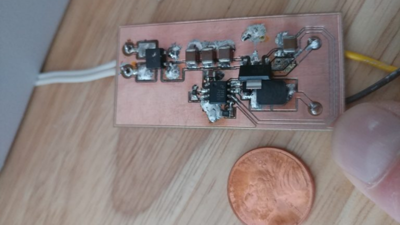
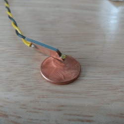 Usually, such builds are plain vanilla and not much to write in about, but [smellsofbikes] has a few tricks worth taking note of. He found a couple of high power, SMD LEDs in his parts bin. They were just slightly wider than 1.6 mm across the terminals. So he took a piece of double sided, copper clad FR4, and edge mounted the LED against one side of the PCB piece, twisting it slightly so he could solder both terminals. This works as a great heat sink for the LED while still having a very narrow profile. This was important as the replacement LED board had to fit the cylinder in which the original lamp was fitted.
The LED is driven by a constant current buck regulator, powered by the original 17 volt transformer. A bridge rectifier and several filter capacitors result in a low ripple DC supply, for which he used the KiCad spice functionality to work out the values. The LM3414 driver he used is a bit off the beaten track. It can run LEDs up to 60 watts at 1 amps and does not require an external current sense resistor. This was overkill since he planned to run the LED at just 150 mA, which would result in a very robust, long lasting solution. He designed the driver PCB in KiCad, and milled it on his LPKF circuit board plotter. The nice thing with CNC milled PCBs is that you can add custom copper floods and extend footprint pads. This trick lets you solder either a 0805 or a 1206 part to the same footprint – depending on what you can dig up from your parts bin.
What left us wondering was [smellsofbikes] statement that “The only annoying bit is it (LM3414) also needs to have its enable pin tied high, but the enable pin has a max voltage of 5.5V, so I have to derive 5.5V from the 20-ish volts of the rectified transformer voltage.” Looking at the LM3414 datasheet, there is a VCC output on pin 1, derived from an internal regulator. From the data sheet, “The VCC provides self bias for the internal gate drive and control circuits.” We are not sure why this could not be used to tie the Enable (actually the PWM pin) to 5 volts without having to use an external regulator. Instead, he added a SOT-23 regulator in his design to get the 5 volt to enable the driver. But the regulator he had on hand had an odd, inverted pin out, and had to dead-bug solder the SOT-23 LDO to make it work. Eventually, it all worked out great, so we guess all’s well that ends well.
To fit the LED PCB in side the original cylinder, he designed a 3D printed collar with tapered fingers which hold the PCB without having to use any fasteners. For the main PCB, a simple 3D printed housing was used to fit it inside the transformer box. Even at 150 mA drive current, the LED lamp is mighty bright, and the over-kill driver will make sure he doesn’t have to worry about a burnt out lamp any time soon.


Huh, good point: I’ll wire from the reg over to the enable line. I’m kicking myself for not having done that.
By the way if anyone else decides to look at this, the LM3414 was good for switching 1A, but the tps92511 was its cost-reduced sibling that only handles 500mA. In general with a buck regulator you want to operate >20% of its max rated current, as that’s where its efficiency is highest. So if you’re running lower currents look for a good current match.
Congratulations on the successful build. I bet it will run for a long LONG time.
First I would like to encourage you to look into eye safety using the LED as a replacement. You are pushing out few enough lumens that I would guess it is OK, but I also know enough about working with lasers to know they can be surprising in a terrifying way. Is your setup similar to known eye safe setups? From the couple of pictures in your posts it looks like the light is not being shined directly into the objective lenses, but reflected off the work piece, is that right?
Also, your solution is small enough that I wonder if you could have repackaged this and stuffed it in the original bulb reciprocal? I could not tell from the the pictures if you could harvest the old connection in the bulb and epoxy, or used potting compound, to make it ridged. If you can get this to work without having to modify the microscope internals, you might find an actual market for LED replacement bulbs that fit into old equipment. I could see building one (if I had a microscope, and needed a replacement bulb, which is a problem I WISH I had ;-)
Again, NICE BUILD!
24V AC LED replacement ES bulbs do exist.
https://uk.rs-online.com/web/c/lighting/led-lamps/led-indicator-lamps/?searchTerm=LED%20bulb&applied-dimensions=4294884947,4294884881,4294867287,4294566233,4293621128
But I doubt that they have the required sort of light output, they are intended for indicators rather than for illumination.
It’s also debatable how well they would work at 17V (was that P-P or RMS?)
When I was doing a lot of microscopy the hot ticket was fibre-optic illumination. But that was (and probably remains) something that you only buy when you have been given a generous equipment budget.
The transformer said 12VAC (so like 9V RMS) but what was actually coming out of the transformer was more like 17V.
And yeah I’d love to do a fiber optics setup some day.
As to previous question, yeah this is shining on the workpiece not into the optics. I work in LED driver IC design and test (I worked on this particular chip) and we’ve learned some things about LEDs that are vision damage hazards. I wouldn’t look straight at this LED but once it’s gone through the optics lenses and expanded a bit it’s well within safe ranges. (And I have equipment to verify that.)
Cool. Thanks for following up with the info. I figured you probably did know that they were eye safe, but thought I would mention it just in case, also as food for thought for others reading here. BTW, I helped maintain a couple of IR lasers (95 and 125mJ with a 11 and 9ns pulse respectively — NO where near eye safe).
Yeah, my previous career was in high power lasers, UV and visible, and I had multiple coworkers who had either partial retinal damage or DIY lasik, people who were PhD’s with years of experience before their accidents, and decided I wanted to go do something less dangerous with my life, so now I play with high power LED’s.
(interesting realization: sure you can see visible lasers and know where they are, but they also nuke your retina. In contrast, you only realize there’s a UV laser problem when you see your skin fluoresce and realize you just got a second degree burn, but those never get through your cornea and you can get new corneas.)
A little bit OOT, but about eye safety: i’m wondering if high power IR LEDs could cause damage to eyes? IR light is invisible to the eye, but the combination of high power source + fully opened pupil in the dark means that a lot of infrared radiation can reach retina.
I was thinking of using a webcam with powerful IR lighting to monitor wildlife nests (birds, hedgehog…), but i’m afraid to cause damage to these animals’ eyes…
It has been awhile since I had a need to check the literature on laser eye safety in wind animals, but I do remember that there is a good deal f literature there. Also remember that many animals and insects do not see light in the same spectrum that we see things, so what is safe for us is not always safe for other little beasties. I also applaud your concern for the animals, and know that there are scientific papers out there that has studied their safety limits as well. Please know that along these lines there are night vision security and wildlife cameras which are specifically made for this purpose, and probably made at least a little effort to be safe to wildlife. I would suggest starting with searching on scholar.google.com and then checking specs on wildlife cams, and then building your own if you still wanted to. On thing that I have never seen is to set up multiple IR illuminators around a space (pointing away from the camera) so that none of them are VERY bright, but you end up with a similar overall brightness.
Also remember that there is a lens in the eye that focuses light onto the retina, so you do not have to have a very powerful beam of light focusing down to a point to burn spot holes in your retina. Also do not think that if the pulses are very short that they are safer — pulses less than 10ns and enough power can vaporize the ocular fluid in an eyeball and the expanding bubble will send a shock wave through the eye which can cause a lot more damage than the single point burn to the retina. Hmmmm… it has been more than a decade since I’ve had my laser safety training review. Hackaday would be a good place for a laser safety post.
I don’t think you’ll manage an IR source bright enough unless you manage to invent the IR flash bulb and trigger it at a few hertz.
However, just thinking about laser safety, why the hell are visible red lasers even of the very weakest output used as guide lasers for IR??? It makes the eye focus the very closest it can to being in focus for the IR, whereas if you used faint blue or green the eye would be quite off focus for the IR.
No no no, don’t panic, it’s quite normal I talk to myself… Beeeecause, if you use a frequency that’s way off from the IR it’s kinda useless as a guide laser, put it through a prism, and your blue beam is over hyar, and your IR beam is 10 degrees or so off over hyar…. so pointless as a guide to see where it’s going through other optics and I guess by the time it’s hit something else pointless for eye safety as you could be looking right down the IR while the blue is sailing past your head at a “safe” distance.
My first thought on this matter was that it is very unlikely that your illumination will be anything like as bright in the IR range as the sun. So I was tempted to say that there was little chance of danger.
But then I considered that many of these animals do not go out in the sun, and if they do then they will have their pupils closed-down, which probably would not be the case at night under your IR illumination.
I think as a starting point I would compare the illumination level of your IR source to that of the sun. If it was 10% then there might be some concern. 0.1% probably not.
I was thinking that if you try to look directly to a powerful standard LED light (visible light), let say even only 15W one, and for a long time, i don’t think it will be very good for your eye. And you will probably not bear it.
But if you replace visible light by invisible IR, with same power, you will not feel anything, and if in dark, your pupil will be fully open, letting more “light” getting in.
If in addition you put that light in a confined space (nest), very close to an animal… And let it turned on with an animal resting during hours or even days? And some animals don’t even have eyelid to close their eyes.
But same question could also apply to humans: what if you place it direclty above a baby bed, very close?
What if you use very powerful IR LED illuminator (50W, maybe more)?
I’ve found in some Axis illuminator datasheet (T90D30) a reference to “IEC/EN 62471 (risk group 2)”. This standard seems to consider these IR lights: “Infrared radiation hazard exposure limits for the eye”. But you have to pay for it…
But according to: https://www.agcled.com/blog/photobiological-safety-of-led.html
“GR2 – risk group 2 (moderate risk): maximum exposure time of 100 s”
So it seems it would not be a good idea to stare at this illuminator more than 100 seconds. Except if it applies to visible light only?
“The nice thing with CNC milled PCBs is that you can add custom copper floods and extend footprint pads. ”
You can do that with any PCB, whether you mill them, etch them at home, or have them made from a PCB service.
Yes, indeed. You can use it for any kind of home-brew method, not just CNC, or even from a PCB service. Although, when ordering out from a PCB fab service, one would hopefully have the right footprints dialled in.
At work we’re required to use only approved footprints for stuff we send out. Bleah.
What I’d taken to doing with gEDA PCB was few or zero traces and using a voronoi processor to make the maximum size pads for everything on the board. That way it was completely automatic and I didn’t have to make special oversize pad footprints. I haven’t learned how to do that in KiCAD yet.
It’s also a mixed blessing that no soldermask means no having to remember to put in soldermask cutouts (but also lots of potential short circuits.)
https://hackaday.com/2020/07/31/transform-kicad-design-to-patchwork-for-isolation-routing/
kicad to voronoi
Great build! I have a scope that needs a lamp like that- I’ll have to try the PCB trick to connect to the LED and draw away the heat.
I rebuilt an old B&L substage illuminator for a student scope that used a spherical bulb in an Edison base. I printed an Edison base to fit the socket and installed an LED- works great! https://1.bp.blogspot.com/-xsCdwj70jLw/XQvPv8zP8bI/AAAAAAAAZ00/dlhjpqCGR8cfbq7pH_fa5u8vTTjatu9MwCEwYBhgL/s1600/061900021906192225121600125.jpg
Years ago I made a stroboscopic illuminator for a biological scope that used a PIC uC to flash an LED at an adjustable rate. It was great for seeing the moving cilia of protists.
The 3d printed bulb base is a good idea. I’ll have to remember that.
Another solution is to take the dead bulb (presuming that the original bulb is still present), wrap it and break the glass and clean the potting from inside the base and solder your LED (or driver) leads into that and possibly re-pot the base with some epoxy or non-conductive moldable filler. I should point out this is alright for stepped down voltages – you assume all risks for utility level supply. I did something akin to that for a bayonet incandescent to LED conversion in the engine compartment of an SUV. Tons more light, mounted in a position that more reasonably illuminated the engine compartment from about top centre when the hood was up.
[smellsofbikes] > “The only annoying bit is it (LM3414) also needs to have its enable pin tied high, but the enable pin has a
> max voltage of 5.5V, so I have to derive 5.5V from the 20-ish volts of the rectified transformer voltage.”
I’ve seen parts that also have enable pins and regulated outputs, but the regulator DOESN’T operate unless the enable is first asserted. Kind of a chicken / egg dilemma.
I’ve used a white or blue LED powered by a series resistor from the primary power source as a sort of 3-to-4 volt shunt regulator just to drive the enable pin. It works, but I’m not happy about the required power resistor. (It was what I could cobble-up quickly.)
why not a few more LEDs in series and a resistor for current limiting?
Partly because I work in LED driver design, partly because I like the efficiency, and partly because that’d be way too much light, and too much heat to handle in the optics tube. It’s also a lot harder to use this LED mounting system for series strings: each LED would need its own pcb or I’d need to put staggered isolation cuts on the copper, which would be cool but it’d also result in too much heat for the available surface area to dissipate.
Eye safe lasers are typically labeled in milliwatts not watts. 15W to 50W is likely a dangerous problem. That said, I think you may be referring to a LED type light bulb (with diffusers, etc). That should help a lot, but how well I am not sure how much as the original post was about a light source for microscope.
Some time back I was going to post a lengthy followup, but it felt like I’d be grandstanding for my own projects, so instead, let me just point out a few highlights:
* While there is nothing wrong with one-off designs to address a specific need, consider a more generic approach to the circuit and where else it could be employed (esp if the characteristics can be altered with just a component or two). This is, I believe, particularly applicable to lighting circuits.
* If the driver IC supports PWM (EN pins often take simple HIGH/LOW input, but may support PWM for dimming), consider taking advantage of it. You don’t have to use a µC to generate adjustable PWM – a pot, three resistors, two diodes, and cap, plus a gate from a schmitt trigger inverter is simple, compact, and works great.
* in the specific case of microscope illumination, a secondary UV illuminator can be handy.