Just when you thought your 3D printer was hot stuff, along comes a 5D printer. Two doctoral students at Penn State want to add two more axes to get rid of overhangs. This means that instead of supports or breaking objects into pieces, the printer simply orients the print so each region of the part is printing as if it were flat. Of course, 5D printers aren’t really new, even though you don’t hear much about them. However, the paper details a new algorithm that eliminates manually defining print regions and rotations.
You do this all the time manually when you’re setting the print up. For example, if you want to print a letter T, you could print it with supports under the cross pieces or flip it upside down and print it with no support at all. The difference here is the printer can flip the workpiece itself to different angles and can change it on the fly during printing. The printer might print the shaft of the T, rotate it to draw half of the crossbar, then rotate it 180 degrees to print the other half. In all three zones, the print head is depositing materials flat with no overhang. In a simple case like a T that doesn’t really require a special machine or an algorithm, but in the general case, you often can’t just rotate a model to avoid using supports.
The proposed algorithm can take into account how much overhang angle the printer can handle so that it can reorient the model as few times as possible. Presumably, rotating the print is relatively time-consuming compared to just laying down a new layer.
We really wanted to see a picture of the 5D machine in operation, but we didn’t find any actual pictures. However, the video below is of a commercial 5D machine — presumably, you have to set it up manually — and it also shows a good example of how a part rotates to get flat prints. We honestly aren’t sure if the algorithm in the paper has actually been applied to real prints yet. The photos don’t look like the models are actually 3D printed.
We have to wonder if 5D will make it to the consumer 3D printing market. Then the marketing hype will kick in and we’ll have 20D printers driven by the marketing department.
This reminded us of 2.5D printing, but it isn’t really the same thing. If your part is spinning around, it probably adds a whole new level of grief for bed adhesion.


If somebody wants to implement this into Slic3r, I’ll send them a free Smoothieboard (which currently does support 5axis motion btw, even have used it on 5axis CNC mills and 5axis lasers).
Actually I’ll literally send you a free 4/5axis A/B rig too that you can add to a 3D printer to support this.
I could try.
You need to provide some contact information
Any updates on the V2? – I’d think the FPGA on some V2’s acting as a distance sensor monitoring and crash prevention cutout would be a good fit for 5 axis, as even if the slicer is perfected the subtle warping of the parts could cause collisions. For which being detected and perhaps fixed in real time would be good, which is something an FPGA is ideal for.
I’d love one!
Print anything big and heavy and the only way you’ll get it to stick is with superglue. Colour me not particularly impressed.
If you can master the 5 axis tool paths (slicing) for the 3print that is really easily fixed.
All prints start with a conical ring of the same material printed flat, so on the 5 axis the mount is a solid contact point – like seen on many woodworking lathe chucks. Carefully cut off if the print permits and you can then just rub it down and reuse that base too.
Or all prints have a hex/square etc support tower that prints first and is used for the 5 axis manipulation.
I agree just attaching the print to a flat bed like normal won’t work for many filaments and certain models even if made of filaments that stick well.
But that really isn’t the major challenge yet, right now just getting a slicer that can deal with extra axis, and print the right parts in the right orientations is. – With extra axis you have to know your previously printed parts won’t collide with the rest of the machine when you change orientation, so have to order the operations such that parts that need to be printed on alternative orientations don’t get in the way of each other (which in the case of 3 printing might well mean building up a few mm on each orientation at a time for best print speed or doing each and every layer on every orientation with a rotation). Ideally you’d also like the slicer to use CNC kitchens strength testing work to automatically pick the required orientations and adjust infill around the changes based on the objects geometry and printing material as an option – giving you the best strength parts when that matters. For that matter a ‘spiral’ print option using the 5 axis so you don’t need support would be very useful sometimes too.
Modern bed flingers manage to keep parts stuck down pretty well while violently flinging, I don’t see why they wouldn’t stay put when turned 90⁰.
It certainly can work, with some filaments you won’t have much trouble I’d think, but bed flinging its just the acceleration of the prints own mass it has to stay stuck though, with gradual acceleration and deceleration – so its not a high force all at once, and the part is probably thanks to gravity going to try and stay balanced anyway.
Very different thing to have an ever increasing mass hung entirely against gravity, so the adhesion to the bed has to carry all the load. And it would be trying to peel itself off – it would probably stick better upside down..
One has a bending moment at the interface and one does not. The adhesion force is not at all the same.
I don’t know, using spray on contact adhesive I have managed to strip off quite a lot of the top layers of glass on my artillery x1, a few times I thought I was going to have to melt the piece off with a hot knife.
I am literally a year into a project to do exactly this. look at https://github.com/julialongtin/hslice
As many comments imply, in my view it is the slicing part that’s super difficult for these kind of designs. Printers would be come if it was easy to program them.
All the luck for the people who are going to actually try it :).
Well, and having the print not peel off the bed and drop when you’re printing bigger objects with high infill.
Its actually quite easy to bond ABS for instance so well it can’t be released, have a textured frosted glass say surface doped with Acetone/ABS slurry and that part won’t come off without pulling chunks out of the glass (so the print is most likely to break instead) – normal FDM is all about striking the ballence between grippy enough to not shift or warp easily, but when cool actually being removable.
So in this case it is trivially easy to overcome – don’t print the 5 axis on a bed at all. Have a starting geometry of the same plastic that can be clamped in to a proper mount and print directly on that when needed – as long as the part is structurally able to take its own weight (which if its going to be useful and that heavy it should be) – so in effect a bed that is sacrificial, in the same way support materials are now.
The gains of 5 axis means ‘sacrificial’ beds that get printed into the parts and bond as well as the filament is able to itself, giving the part the right direction layer lines for strength etc.
It is ‘quite easy’ when the joint is almost fully in compression due to the weight above it. Add some tension that joint and it may not work so well. Just put some plastic dowel pins in the build plate and bond a few layers to them.
Am I the only one that tilts my printer to help with certain prints. I thought everyone knew that trick?
Huh. Automate the tilt in two directions and you’ve got two more axis. Or maybe a couple half axis for 90 degrees :).
Hmm that could actually be a good 3+2/xths of an axis solution for many prints.
And compared to getting full 5 axis to slice properly, just having it tilt the whole bed within a 70 degree cone? (whatever the machines limits) to avoid printing overhangs is comparatively trivial. Getting the machine mechanicals right could be a challenge though, dynamically shifting the whole printer (which would be the easiest method I would think) is tilting a pretty heavy lump rather fast, or slowing the print speed down alot so it can keep up.
my mind is blown
Print a raft then pause to install a clamp ring to hold the raft edge down. The print won’t fall off.
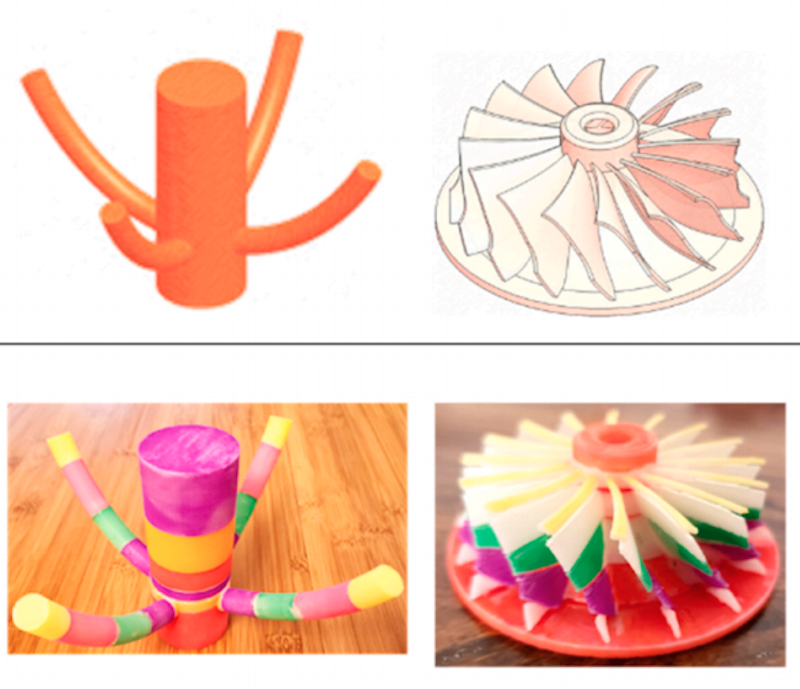
The example of the turbine blade would not benefit from a 5 axis printer until you have a long thin print nozzle, because the shaft is perpendicular to the base the print head could not move into the corner produced by the 2 planes, so the print would have to use the shaft orientation as the z axis. Any deviation from that and the head would either hit the base, the shaft or further along on the print, the blades.
The other example would benefit from 5 axes printer, but again the movement is more complex than first appears.
1st the branches would need to be far enough from the bed to allow the print head and support hardware to not foul the print bed whilst printing the branch.
2nd the head would need to rotate round the shaft for the first few layers, not impossible but it does make the head movement complex.
I’m sure there could be uses for this. Blocky prints would be fairly easy work but curved and tubular parts require additional parameters.
To ensure the print stays on the bed the print could have a sacrificial base a printed on a textured base, to remove the part heat the bed up to near melting point of the material.