For many years now, the so-called ‘Blue Pill’ STM32 MCU development board has been a staple in the hobbyist community. Finding its origins as an apparent Maple Mini clone, the diminutive board is easily to use in breadboard projects thanks to its dual rows of 0.1″ pin sockets. Best of all, it only costs a few bucks, even if you can only really buy it via sellers on AliExpress and EBay.
Starting last year, boards with a black soldermask and an STM32F4 Access (entry-level) series MCUs including the F401 and F411 began to appear. These boards with the nickname ‘Black Pill’ or ‘Black Pill 2’. F103 boards also existed with black soldermask for a while, so it’s confusing. The F4xx Black Pills are available via the same sources as the F103-based Blue Pill ones, for a similar price, but feature an MCU that’s considerably newer and more powerful. This raises the question of whether it makes sense at this point to switch to these new boards.
Our answer is yes, but it’s not entirely clearcut. The newer hardware is better for most purposes, really lacking only the F103’s dual ADCs. But hardware isn’t the only consideration; depending on one’s preferred framework, support may be lacking or incomplete. So let’s take a look at what it takes to switch.
The Hardware
The F4 MCUs have significantly better specs than the F103, with a higher clockspeed, more flash storage and more SRAM. In total we have three MCUs to compare on the old and new boards:
- F103: 72 MHz, 64/128 kB Flash, 20 kB SRAM. (STM32F103C8T6)
- F401: 84 MHz, 256 kB Flash, 64 kB SRAM. (STM32F401CCU6)
- F411: 100 MHz, 512 kB Flash, 128 kB SRAM. (STM32F411CEU6)
The Cortex-M core in the F103 is the M3, whereas the F4xx has an M4 core. For the CPU side of the MCU this effectively means that in addition to higher clockspeeds we also get the ARMv7E-M ISA, instead of the ARMv7-M of the M3. This adds full saturation arithmetic instructions, DSP instructions and optional single-precision floating point instructions. Both the F401 and F411 have a single-point FP unit, and are thus much more suited for floating point arithmetic than the F103.
More detailed differences can be found when we look at Application Note 4904 (AN4904) from ST: Migration of microcontroller applications from STM32F1 Series to STM32F4 Access lines. This document summarizes all of the differences between the two MCU families worthy of note when migrating from one to the other, whether for the physical pin layout, peripherals or the bootloader.
Here the biggest changes are probably in the memory layout, along with the number of certain types of peripherals. Feel free to compare along with us in the block diagrams.
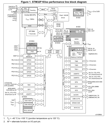
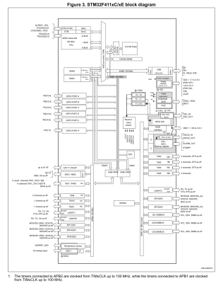
A significant change between F103 and F4xx is that the GPIO peripherals were moved off the Advanced Peripheral Bus (APB) onto the AHB. AHB is the high-performance bus, for high bandwidth, low-latency operations. It is connected directly to the Cortex-M core via the AHB bus matrix. The APB on the other hand is a simpler bus, with no burst operations. Accessing peripherals on the APB from the Cortex-M core requires that the instructions pass over the AHB-to-APB bridge to the APB.
This should mean that GPIO operations are faster on the F4xx MCUs, especially with high-frequency operations. In addition, the I/O pin multiplexing on the F4xx MCUs changed to only allow one alternate function (AF) to be defined for a single GPIO pin. This corresponds to the integration of AF registers in the GPIO peripheral.
A big change is also seen in the RTC peripheral, which on the STM32F1 family is a simple 32-bit counter with programmable prescaler and an alarm register. On the STM32F4xx the RTC peripheral implements a full calendar, with sub-seconds, seconds, minutes, hours, days, months and years. It also has an alarm which can be triggered by any of these calendar fields, as well as an event time-stamp feature and a digital calibration circuit.
While DMA, the FLASH interface and Interrupts also see some changes, these are fairly minor and only of relevance when doing bare-metal programming. The one real gotcha with the F4xx chips is that in place of two 12-bit ADCs with 16 shared channels, the F401 and F411 have a single 12-bit ADC. For the trade, the ADC is marginally faster on the F4xx (2.4 Msps versus 2 Msps on the F103) and has a lower minimum voltage supply requirement of 1.7 V -1.8 V.
The Pills
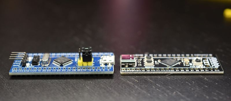
The differences between the two boards are quite stark, even beyond the soldermask color. The board which I am comparing with here is the STM32F411 version, which incidentally seems to be the most popular version when I searched for these boards on the German Amazon website.
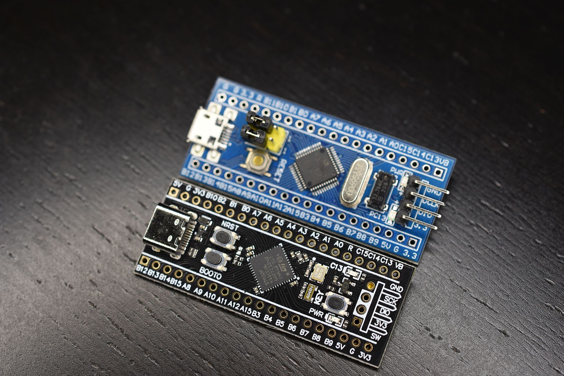
The USB connector changed from micro USB-B to USB-C, the MCU package is a 48-pin UFQFPN instead of a 48-pin LQFP, we get an extra user button, and the HSE and LSE oscillators are much smaller. The boot mode pins are gone, but we get a boot mode button instead. We keep the same user-controlled LED on PC13, but the pin-out on the sides of the boards are not 100% compatible. Finally, one ‘Ground’ pin has been replaced with a 5 V pin. (!)
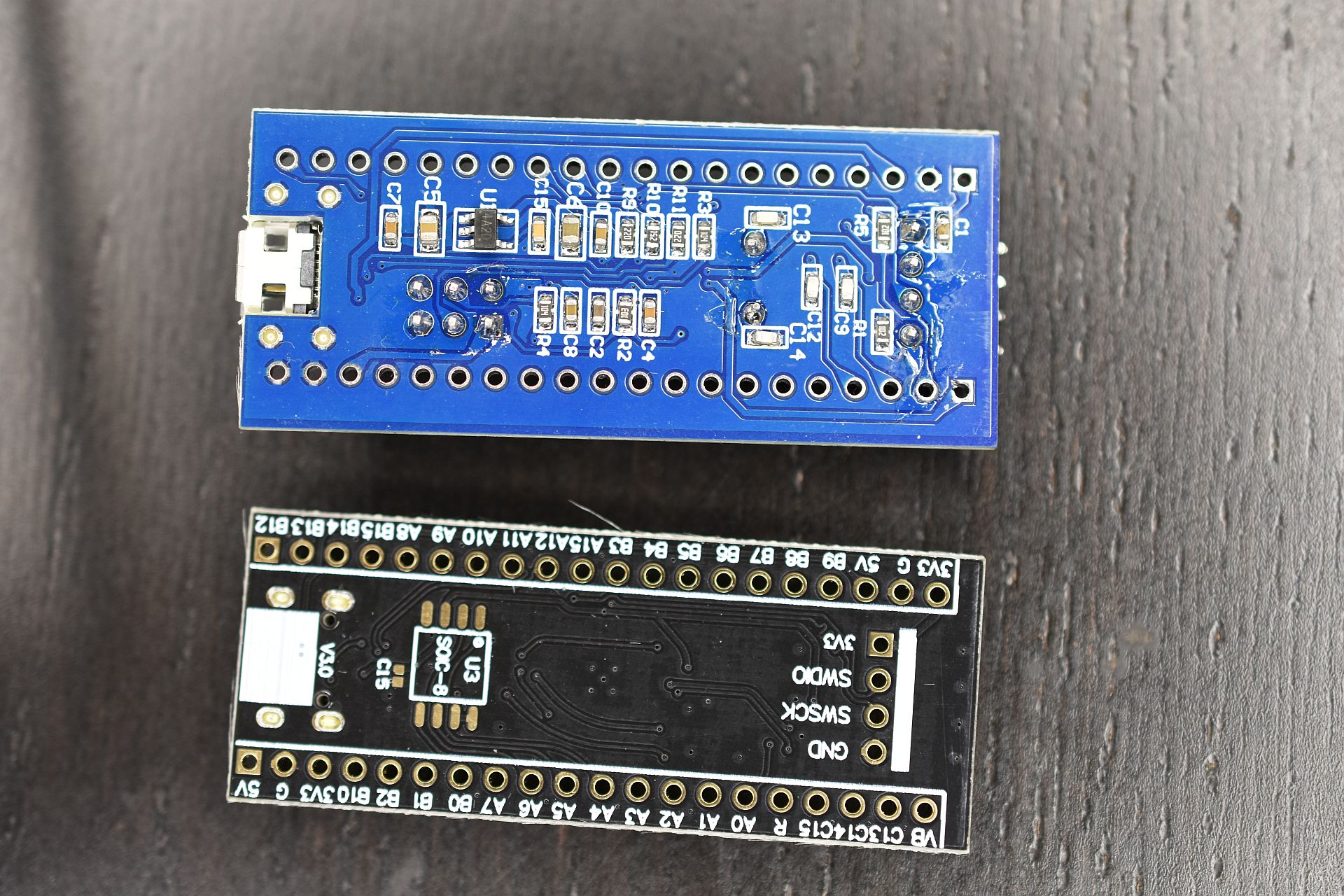
Flipping the boards over, the F103 board features a heap of passives and one IC, while the F411 board is clean except for a footpring for an SPI ROM footprint that fits an W25Q32JVSSIQ 32 Mbit SPI Flash ROM, for instance. This could be used to add a configuration ROM or similar.
Beyond these differences, programming and debugging the board stays the same. One can use serial programming, with genuine STM32 MCUs, Single Wire Debug (SWD) via the four-pin break-out header, or the USB port if a suitable bootloader is installed. The schematic for the board is also available, which refers to the board as the ‘MiniF4’. This schematic also reveals without having to pull out the DMM that the user button is connected to PA0 without pull-up or pull-down resistor.
The Software
The STM32F4 family of MCUs is fully supported by ST’s CMSIS F4 device files, as well as its hardware abstraction layer (HAL) framework. Some may prefer to use ST’s STM32CubeMX software to auto-generate the hardware configuration and setup code.
STM32Duino also shows both the F401 and F411 boards to be supported. Those who are more inclined to meddle with tiny non-venomous snakes should be relieved to know that there are multiple MicroPython definitions for the boards, for the F401 and F411, as well this MicroPython board definition for the F411 version of the board. This means that at least as far as Arduino and MicroPython goes, existing code for F103 boards should run with minimal changes on F401 and F411 boards, keeping in mind potential changes to GPIO and AF pins.
In my own Nodate STM32 project I have added a board definition for the F411 board version as well. The fact of the matter is that these ‘Pill’ boards are such basic break-out boards for STM32 MCUs that very little support is needed. Besides the MCU on the board there’s just the LED on PC13 and a switch on PA0 if one’s framework is the type that abstracts such details away.
Conclusion
There comes a time when one has to move on. Considering that the STM32F103 is part of ST’s first-ever generation of Arm Cortex-M-based MCUs should already hint at that the time may have come for the Cortex-M3. As I noted in my recent article on STM32F103 clone chips, the supply of F103 ‘Blue Pill’ boards has recently become flooded with fakes, clones and brazen imitations of the genuine STM32F103. This makes it hard to even get such a board. Unless one is ready to validate and accept certain of these (admittedly quite good) F103 clone MCUs.
Meanwhile these F401/F411-based ‘Black Pill’ boards do not seem to have any issues with clones or fakes so far, cost roughly the same per unit as the older F103 ‘Blue Pill’, and unless you absolutely need the second ADC unit, are a better deal all-around. Software support should pose no obstacles either, with even details like the user LED using the exact same pin.
Just make sure that that you keep the slightly different pin-out of the F4xx boards in mind (i.e. the new 5 V pin), and double-check against the F401 or F411 reference manual to ensure that the peripherals one uses in a project are still on the same pins after recompiling for the new board. For new projects, using these new boards seems like a no-brainer, which is why I’m pretty sure that I’ll be stocking up on them.
What will your stockpile of cheap STM32 development boards look like the coming years? Will you be switching to F4 MCUs, or sticking with those F103 boards, if only because you bought 75 of them in an auction once and still haven’t used them up? Do you have any special use cases that make the F103 more suitable for your projects? Please let us know in the comments.


What I want to know; are counterfeit STMs infesting the Black Pill products as well?
Doh!
I posted before reading the full article.
Pass the crow, please…
with 3.0 version they moved the F401 version to STM32F401CE – 512KB ROM, 96KB RAM – see https://github.com/WeActTC/MiniF4-STM32F4x1
I hear too much FUD about the different F103 chips on the blues, and not enough about what kind of random chips you get on a “black pill”. There are at least three chips from the F4xx family that are all available.
Good news is that they’re all broadly similar, but woe unto you if you need any particular features.
In contrast, I order blues by the 10-pack, and haven’t gotten a counterfeit yet. This last time I knew I was ordering the GDs though, and got them. No harm done.
they also made a refresh of blue pill with F103 https://github.com/WeActTC/BluePill-Plus in same style with usb-c and sell it e.g. here https://www.aliexpress.com/item/1005001474741936.html that one is not so cheap but possibly have real stm32 chip. Might make sense for those wanting to stick with F103
The uTasker project on Git hub [https://github.com/uTasker/uTasker-Kinetis] runs on, and simulates, the original Bluepill: [https://youtu.be/dq-m-Dokq7E] and includes STM32F4XX support, allowing STM32F1XX projects to run also on the the STMF32F4xx. Therefore, both Blue and Black pills can be used!
The F411 has a better USB peripheral too.
Can you say more? I’m curious to know the improvements. Thank you.
It has a much better DMA design, so it can actually run at full bus speed. It also has more memory for USB packets, and it uses the memory more efficiently.
Thank you! I wonder if it will do a better job of being a Greaseweazle? https://github.com/keirf/Greaseweazle
Better seems to be relative, it’s also more complex to program and has fewer endpoints available in device mode.
On the upside it supports host mode…
This depends on what you consider “better”.
The F401/F411 only support 3 endpoints per direction, which limits the number of CDC-ACM (serial) interfaces to 1. The L4xx e.g. support 6 EPs per direction, the F103 allows up to 16 Endpoints (any direction), so this is a significant step backwards.
The STM32F4s, at least the 401 from the Nucleo, are very well supported by the Mbed APIs. I think Mbed’s a nice middle ground between Arduino and something more advanced with features like timers and interrupts fully abstracted, even RTOS support.
+1 for Red pill
Or, you could realize we use a context based language.
Some phrases and terms, have very limited appropriate contexts, usually just things like condemning the use of said phrases, quoting their use and repeating historical texts.
Wow, the bluepill in the picture has the correct 1K5 R10 value for the D+ line pull-up. I wonder if it’s reworked!
Great article, like all the ones by Maya Posch on STM32 chips, kudos.
There are different versions of the Bluepill, the ones with the four legs on the USB connector and the flat button seem to have the correct resistor, the ones with two legs on USB and the taller button do not.
Where can I find cheap boards with original stm32 mcu? Seems all of them now on cloned chineese stc32 or remarked chips
Yeah they are not $1.77 anymore. $3 and up.
128 kB is a lot of RAM for a microcontroller. You could probably emulate a VT320 or maybe even VT340(+graphics) with it. Given the price of old serial terminals in working condition, it might even be the cheaper option.
Maybe you could put MicroPython on it?
The internet says microphone needs 256k
I think everyone will be going to the pimicro
You know, not every English speaker/user lives in America where everyone seems to be hell-bent to look for stuff to be offended by, context and actual meaning of the text be damned.
Here you have the board schematics:
http://uglyduck.vajn.icu/ep/archive/2020/11/STM32__Pill__boards.html
Thank you! I’ve tried to find the bill of materials for the original schematic because a lot of the components don’t have they value marked there, but this is so much better!
The black pill I have as a STM32F411CEU and under side there is a Winbound 16MB SPI flash installed as U3. So it is possible to get a black pill with U3, C15 installed. Check for it when ordering.
Can you tell us where you ordered yours from?
Thanks.
https://www.amazon.ca/-/fr/CANADUINO-STM32F411CEU6-100-Flash-programmeur-d%C3%A9bogueur-ST-Link/dp/B0847G8RQF/ref=sr_1_7?dchild=1&keywords=CANADUINO&qid=1611179179&sr=8-7
but available in single unit here:
https://www.universal-solder.ca/product/stm32-pro-black-pill-stm32f411ceu6-128m-extra-flash-100mhz-512k-internal-flash-128k-ram-no-soldering/
My first reply was blocked, maybe because of the links in it, Search for universal-solder dot ca
This is a company in Saskatchewan, ca. I think that U3 addon is a of their own.
Thanks!
BTW, I’ve not checked the docs, but anyone know off the top of their heads what capacitor to use for C15?
typical IC decoupling capacitor – 100nF (“104”), size 0402, x5r or x7r ceramic, for any max voltage (6.3V…50V), any tolerance (20% acceptable)
@yurly
Thanks!
+1 for Universal Solder. As a Canadian it is nice having a source of diy electronic parts within our borders. I’ve used them a couple times. I’ve been impressed with the quick delivery times. The documentation is a little lacking though.
i am a novice at hardware stuff, what is the big advantage of on board storage? is it to stor sprites (?) or graphics for a display that you might hookup? or more for like datalogging (though i use an sd card module when i’m doing this).
Depending on the application an SD card module can be an overkill. Say you want to do some audio synthesis 16MB of flash can store a lot of audio samples. This is just an example. The fact that it is soldered on board it is more sturdy. Reduce contact failure. No risk of being dislodge because of vibrations as it could be the case with an SD card. All depend on application requirements.
thanks!
black pill, blue pill, arduino (uno, due, mega, leonardo, lilypad, esplora), hat (just name a few), pi, beaglebone (beaglebone black)…
I guess I’m getting old, because where I come from the base/core of a design used to have numbers… 555, 741, 6502, 74XX, 40XX those were the days. Far less complicated and with clear datasheets and everything was expensive (although that wasn’t really a good thing). Sometimes I think I was born 20 years too early, all those nice things to choose from these days.
You’re getting old. I recall building Z80s and 8051s with HEX coded assembly language saved on a magnetic cassette using 1200 baud for a 1 and 2400 baud for a zero. Wire wrap anybody? Now those were the days.
Yes !!! Wire Wrap. Fast and Flexible.
Not to mention bulky and unreliable!
Seriously – there’s a reason wire-wrap went out of style. Bulky: your DIP package ICs might be 10 mm thick, but add a socket, and suddenly they’re four times as thick. Unreliable: the connections themselves work well enough, but make the slightest nick when stripping wires, and they eventually break right at the base of the wrap. Oh, and expensive – those sockets cost 3-5 times as much as the chips, or even more if you bought “proto” boards with sockets pre-installed.
I think you mean 1200 and 2400 Hertz. Baud is a measure of symbol rate, for ones ans zeros combined, so what you say is somewhat like saying your car gets 35 minutes per gallon.
Black and Blue Pills, low cost, good value, provided that you receive what you thought you were ordering.
15 years ago when I first encountered the Arduino, it cost $20.
If you have $20 in your pocket today, my advice would be to buy a 600MHz ARM Cortex M7 Teensy 4.0.
Besides the clear power of the iMXRT1062, the Teensy is a consistent experience. Every single one I have bought is exactly the same. I based a product on it because of that. I looked at first the Blue Pill and then the Black Pill. In either case, there is a real lack of consistency (as you noted) in the Pills. I bought a number of pills and notne of them were exactly the same. I can’t imagine supporting a product that uses a Blue or Black Pill. Whata nightmare.
For a hobbyist, the Teensy is a far better experience due to the Teensyduino environment. The broad selection of libraries pretty much just work and there is a very supportive forum.
If you go for the more exotic STM32 chips (I know they are more expensive) like the stm32h743 or stm32h7450 then there is a much smaller chance of getting fakes. Also if you want to use a STM32 MCU in a project you could just use a nucleo or discovery board and then transition to a custom PCB for your final product which is what should be done anyway to make sure it is as cheap and reliable as possible.
I ordered a BASIC Stamp from the back of Nuts & Volts magazine for $$$. I eventually stepped up to programming naked Scenix/SX chips in assembler just to get away from the cost of Stamp modules. Often scavenging old projects for idle Stamp modules.
Now with STM32 on “Pill” modules and ESP-based modules for cheap, I don’t feel the need to do the extra work for getting DIPs on a breadboard with vendor-specific “in system programming” adapters. I can get a module for under $20 and tack some wires on or modify it for a project and just leave it in that project forever.
(sigh) I’m still waiting for my black pills I ordered last November. damned you, covid! lol
“The one real gotcha with the F4xx chips is that in place of two 12-bit ADCs with 16 shared channels, the F401 and F411 have a single 12-bit ADC”
Does the F4 ADC also have shared channels?
No, because there’s nowhere to share, since it’s a single adc.
The real question is; how many channels?
Some low level code to access the serial flash rom and other peripherals can be found over here https://ioprog.com/2021/01/15/the-stm32f411-black-pill/
if you head on over to the stm32duino.com forums you will see we have a lot of example code, bootloaders, programmers, tricks and tips for stm based boards.
the stm32f4 chips also feature an onboard floating point processor. So if you happen to be doing some maths on your microcontroller that is very hady.
For those looking to try something different, there is rudimentary Kotlin Native support for the STM32F4 series
https://github.com/JetBrains/kotlin-native/blob/master/konan/platforms/zephyr/stm32f4_disco
Maybe a better link to get the flavor of embedded kotlin
https://github.com/JetBrains/kotlin-native/blob/master/samples/zephyr/src/main.kt
I just currently bought a blue board and ordered a black 411 board. Still waiting for FTDI serial to burn arduino bootloader to them. I am still using atmega 328 and 25something.
As far as I understand WeAct seems to be the original manufacturer. Got five apparently original boards from them and I really like the PCB quality. On their GitHub they offer detailed instructions on how to identify counterfeit / clones boards and they list a few shops one should not consider to buy from. Currently I’m waiting for their STM32H7 boards to arrive.
I bought one from my local dealer, looks like an WeAct here as well.
So, here’s their GitHub
https://github.com/WeActTC/MiniF4-STM32F4x1
and in regard to my earlier question about counterfeits, their Readme says…
“Recently, online shopping platforms have seen a large number of counterfeits, that is, pirated copies. We found that these counterfeits do not have WeAct && version Numbers on the back.And the boards are not lead-free, and we all know that lead is bad for you.The chips are not the latest batch, or even refurbished”
I do not really want to swallow these “pills” anyway. So the health argument is not really valid – and for my private projects or lab work I use the good lead based solder anyway.
Also got 2x WeAct boards off aliexpress. Top quality boards! Loaded QMK onto one via DFU (USB)
A lot less faffing around than the bluepill that I managed to brick for no apparent reason…
Chinese product gets pirated by Chinese producer. Oh, the irony ..
Umm.. Open source design. Manufactured by many firms. That’s called competition, and it’s the crux of what makes free markets work. Hooray!
Literally seconds after release of the “black pill” the Chinese started selling “blue pill” boards colored black but still based on the old flawed “blue pill” design. Still to-date, you have no idea what you are getting when you buy a blue or black colored board from China. Almost all of the blue or black (or whatever color) boards from China come with counterfeit STM chips on them. They work for simple “blink” applications, but beyond that you can’t count on anything. For any sort of real application, stick with the manufacturer’s dev boards and only buy from known trustworthy distributors.
Just by the way, at least the F411 supports programming over USB without installing a bootloader. It would require a reset with the boot button pressed though, to get it to boot from ST’s built-in bootloader, which supports DFU.
Concerning that ‘faster’ ADC, this seems like a good place to ask. Has anyone done any tests to verify the R_ADC value for 3.3V operation? The F103 lists it as 1k max (guaranteed by design), but the F411 datasheet says “RADC maximum value is given for VDD=1.7V, and minimum value for VDD=3.3V”, but in the table it only lists 6k as the max value and under min there’s only a dash. This is actually quite important if you are running at 3.3V and want to take advantage of the full speed and full resolution, as for max speed max resolution you’d need at most a little over 1k total of the internal R_ADC and your external source resistance, which is completely unattainable with 6k of switch resistance.
I’ll do my own tests in a week or two when my custom F411 boards arrive to find out if the switch resistance at 3.3V is low enough to get away with 0.1µs sample time (that’s 3/f_ADC @30MHz, the fastest it can go) or will I have to settle for the next lowest value of 15 cycles (0.5µs sample time). In either case, there’s still the 0.4µs required to perform an actual conversion, so the difference in full conversion time is really 0.5µs vs 0.9µs.
In the case of the F103, they might have a customer that asked for the specific ADC specs, so they designed for that. In either case, they don’t test it for production as it is not so easily determined. You would assume that their engineers that design the ADC block know what they are doing.
The only thing to go by is look at the GPIO VOL/VOH at 1.7V vs 3.3V parameter and use that as a very rough ratio of the RADC at those 2 voltages. This is assuming that the ADC MUX transistors are similar to GPIO transistors and behave similarly. So you’ll get at least a factor of 1/2.
Micropython is a great choice for DIY programming, and this was one of the reasons why I’ve switched to BlackPills.
Micropython makes communication with periphery much easier comparing with Arduino or STM LL/HAL code.
IIRC the ADC for stm32f103 is not 2MSPS, but 1MSPS.
There’s a ‘dual’ mode (or whatever it’s called), where you could reach 2MSPS by using both ADCs. But it’s not really the speed of the ADC. In this regard, the 104 has dropped one ADC, but for a faster one (more than double)
Both the 401 and 411 lacks CAN, so it’s a showstopper for me. Until boards with 412 or 413 shows up, I’m sticking to the 103.
So very much this :(
To other people, if it’s any consolation usb and can couldn’t be used at the same time on the f103 series. They had this weird dma setup where both peripherals shared the same memory. Wasn’t fixed until the “connectivity line” (f105 and f107), and well, everything that isn’t the f100 series.
Sure but when I put a CAN-connected device like a PLC into a system, it does not need USB. It’ buried in a wall or machine or something.
If you want a CAN bridge, put a CAN device on a Pi. Use a real network interface and real OS :)
Would be very happy to see a more modern x-pill appear with CAN and more grunt though…
I will go read the data sheet, but does the current STM32F103 still suffer from the I2C “silicon errata” problem? Is it fixed on the 32F411?
I believe it is fixed on the F411
Neither the F401 nor the F411 have a CAN bus. The F103 does. As I use the pills for home automation with a CAN bus, this is a K.O. criterion against use of these black pills – as much as their hardware is tempting otherwise.
On the topic if STM32F4, check out the stm32f407vet6 boards on Ebay. They’re about $11 but have soldered headers, an NRF24L01 socket, microSD socket. They run at 168MHz, have 192KB SRAM, 512KB flash. I have lots of the stm32f103c8t6 boards but have started to port all my code to the F4. It has been a painless transition. The built-in FP unit of the F4 is nice. Vastly speeds up computationally-intensive code. Be forewarned. The reference manual on the STM32F4xx is 1751 pages long! Quite a bit more than the STM32F1xx, LOL…..
Has anyone a source for blackpill with stm32f407? I need can bus and the 401/411 lack of this.
Was it really only a year ago that the blackpill STM32F411 came out? I bought mine from Pimoroni. I did have a clone bluepill before that. They were a real fiddle to work with. Often code wouldn’t upload, and just a general nightmare to deal with.
The way I like to work is with the Nucleo-64 F411 board. You just can’t beat the integrated ST-Link. Then, when I’m happy that everything works correctly, I transfer my code to the blackpill.
Time to switch to ARM M33 on STM32H5xx . Almost pin compatible to STM32F103 on old Bluepills.