For anyone involved in the construction of small electric vehicles it has become a matter of great interest that a cheap high-power electric motor can be made from a humble car alternator. It’s a conversion made possible by the advent of affordable three-phase motor controllers, and it’s well showcased by [austiwawa]’s electric bicycle build video (embedded below).
The bike itself is a straightforward conversion in which the motor powers the rear wheel via an extra sprocket. He tried a centrifugal clutch with limited success, but removed it for the final version. Where the interest lies in this build is in his examination of Hall effect sensor placement.
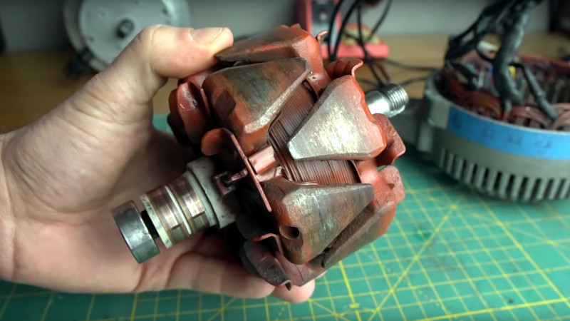
Most alternator conversions work without sensors, though for better control it’s worth adding these magnetic sensors to allow the controller to more directly sense the rotation. He initially placed them at the top of the stator coils and found them to be ineffectual, with the big discovery coming when he looked at the rotor. The electromagnet in the rotor on a car alternator has triangular poles with the field concentrated in the centre of the stator, thus a move of the sensors to half way down the stator solved the problem. Something to note, for anyone converting an alternator.
Should you wish to give it a try, a year ago we published a primer on turning car parts into motors.


Another oddity of alternators is the output waveform: triangular. Driving these motors may benefit from triangular inspired PWM.
The second oddity is that the Kv of the motor changes with the rotor current, in an inverse manner, so the motor spins faster when you put less current in through the brushes. This has the undesirable consequence that when your field excitation battery is running low, the bike starts to speed up faster and faster, but also it starts to gulp a ton of current at low speed because the back-EMF goes way down.
The next addition would be to wire the field battery out of the main battery, and add a current regulator to keep the motor constants… well, constant.
Or alternatively, short the field coils internally and turn it into a three-phase induction motor, and change the controller into a VFD.
So, relate RPM to field weakening circuit, such that Ya only weaken the current as Speed picks up.
Additionally, strengthen the field to the max allowable when Bicycle needs to “hold Back (brake)” and reclaim some energy! Both were features of Controllers on Container Cranes I spent My Career on.
Depends on what you want to do. It works kinda like series/shunt wound DC motors – except if you connect it wrong you can create a motor that will explode on you because it keeps speeding up the more it speeds up.
Other things to note when converting an alternator to motor usage:
Alternators and CD drives both commonly are 12 pole pairs, you can take the magnet ring from a CD drive and attach it to the back shaft of the alternator. It makes an easier way to mount hall effect sensors without opening up the alternator. This arrangement also gives you the ability to time the hall sensors to optimize the hysterisis in their switching for a different rpm. With neutral timing (as achieved by embedding the sensors like this video) you end up optimized for low rpm, at high rpm the controller ends up spending part of a phase fighting the rotation because its sensors haven’t caught up yet. You can advance the timing some to account for the switching delay, this makes high speed operation better because you arent running in reverse for part of the phase but it means that at low rpm you have the same reverse powering problem.
The rotor field saturates at 12v so attaching a battery greater than that will just result in more current without increasing the field strength. As mentioned in a sibling comment you can change the kV of the motor by tweaking the field current, but in my experience the kV stops going down once you get past 12v on the field.
The stator field doesn’t saturate until you are pushing about 400 A. There is a linear relationship between stator current and torque up to that point. I dont recall if the 400 A limit was due to saturation or due to us not being able to experiment due to motor controller limit.
Also, you can push an alternator much harder than a bldc because you don’t have to worry about heat causing the magnets to weaken. In an alternator you just have to worry about winding insulation breaking down, bearing grease boiling out, and wires coming un soldered. All of those failure modes are much higher temperature than the magnet weakening.
In my experience using an alternator as an adjustable electric brake, the field keeps going up to 15-16 volts or so. Technically it never stops increasing but you just get diminishing returns.
Okay!
How about dynamic braking?
Or how about charging when comes to coasting as well.
Any takers out there??
Sadly only in french but very relevent: https://youtu.be/Sft0eyTIXFQ.
The alternator is made brushless and the sensors are opticals.
Alternators used in cars are not very efficient in generatiing and thus will not be very efficient as motors. In automotive use they were not made to be especially light in weight. With light and efficient motors from China, it may be bwtter to get a motor from there and add your controller to it?
It’s true that an alternator will never be as efficient or as good as a similar permanent magnet motor.
The advantage here is price and availability, you can have one on your bench within hours for a tiny fraction of the cost of an equivalent PM motor.
Maybe minutes, I’ve got a couple of alternators in the corner of the garage, with lawnmower motors, old UPSs, a kind of hackathon waiting to happen if the power looks like being out for more than a few hours. So I could just go in there, dig in that pile of really interesting junk, that probably has several other fascinating pieces that I forgot about… yeah you’re right, hours.
And their cray ruggedness.
Compared to most motors, they thrive on abuse and neglect, well except the brushes and slip rings for such.
But that also means that with higher voltage rated diodes (so they don’t die), you could tweak them to spit out a higher voltage with a different regulator.
On vehicles, the bearings seem to go if they’re too near the grille (spray) and the diodes or regs seem to go when they’re too near the manifold (heat) that’s after 10 years of either though. So exposed as in this application, you’d want to be nice to the bearings. Replace with good quality sealed ones… the seal starts cracking up after a number of years… however, you can lube it yearly with moly bearing grease and a sawn off basting syringe, and smear RTV over the cracks.
The efficiency of the alternator is entirely dependent on the use case. In a car, it has to operate over such a large span of conditions that it can’t be efficient.
As a motor, no BLDC motor does very well across the whole power band. In practice almost all of them are just 70% efficient on average.
Sounds a bit picked out of a hat.
A lot of use cases require less torque at lower speeds – fans for example. It’s power output requirement would be vastly different from a constant torque use like a winch.
More info, a reference or a link would be great.
It’s in the ballpark. There’s a logarithmic relationship between RPM and efficiency for a common BLDC motor such that the “knee” point of the curve is at 63% efficiency. I forget how the formula went, but the way most vehicles are built, they try to put the top speed at 120 mph on the highway so you would have the maximum power point around 60 mph – after half the RPM range the power output starts going down – which means you start suffering significant efficiency losses around 30 mph.
With the typical urban traffic, you’re averaging around 30-40 mph with a lot of accelerations below that, which really kills the overall efficiency. If your car was optimized for a much lower top speed, you could probably double the mileage on the battery.
Not top speed, but the nominal RPM of the motor of course. The actual top speed depends on where the falling power curve meets the rising air resistance after you pass 60 mph.
That would work, but it’s still cool to go get one off an old car. So it seems straightforward , as normally it spins to generate power, so reverse it, in that you give it power to create, or make it, spin/turn your wheel, thus propelling you forward.
China is a bit on the nose at tbe moment. We cant all be lazy and just buy evertthing fron China. We will lose our knowledge and skill bases if it keeps up. Better to make it yourself and have some pride all at the same time.
An alternative to internal Hall sensors might be a commutation encoder. This one is programmable for number of poles, and for alignment, and can work with shafts from 9 to 14mm diameter:
https://www.cuidevices.com/product/resource/amt33.pdf
They tend to also provide a quadrature output, opening the door to sinusoidal commutation, if desired and supported by the drive. Or closed-loop position control for, err, no good reason that I can think of.
Hall sensor controllers also do sinusoidal control (FOC), given that the RPM won’t change that much in a hurry.
Technically, any such motor can be driven without feedback as a synchronous motor. Getting even one pulse per revolution allows a controller to check and adjust the field advance so the motor doesn’t stall on a load change. It just doesn’t work well for low RPM operation.
Is it feasible to change out the rotor for a synchronous style solid salient-pole rotor?
The biggest drawback I can see here is that the rotor is basically just a big electromagnet that sucks down a couple of amps .. All. The. Time. Yes, that is so that the 3phs stator can put torque on it (in motor mode) but from a power perspective, this is just dozens of watts lost heating up some copper. Not the most effective use of limited A-hr’s.
A permanent magnet rotor would be what you want in an application like this. Car alternators don’t use PM rotors bc they need to control rotor current in order to get relatively constant voltage across varying engine speeds. Conversely, you *could* control rotor current to get relatively constant torque at varying drive speed .. although what you’d probably want is high torque at low speed and less torque at high speed.
Idk, there’s a probably a reason, after 100+ years of electrical machine evolution, that we still have some machines optimized for electrical to mechanical, and others optimized for mechanical to electrical, and not just some kind of universal electrical/mechanical converter.
When torque is not required, you can dial the field current way down, and also reduce the drive duty cycle (or voltage) to match, which allows you to coast along using barely any power. In a PM motor you have to exceed a certain voltage for a certain RPM to push current into the motor, but in a field adjustable motor you can choose your back-EMF and reduce the idle losses of the motor when high power is not required.
One of the biggest challenges in EVs is that you can’t optimize the same motor for all speeds. If you make it run fast, your stall current goes up and the efficiency at low road speeds goes down. If you do the opposite, you gain good pick-up torque but you lose top speed. Any real EV has to make a compromise between the two, and it usually means you don’t get a high top speed, and you don’t get the best efficiency under city speed limits.
Hence why, most EVs would benefit from having a two-speed gearbox, but this costs money and is actually difficult to engineer because it has to deal with so much torque. A field-controllable motor would do almost the same job by changing the optimum RPM as desired, which can easily offset the excitation loss and then some, but it comes with brushes that wear out and cause EMI.
Some very large industrial motors solve that issue by using rotating axial transformers to drive the field current.
Wonder then if EVs would benefit from permanent magnet motor design optimised for either high or low speed, and supplement (either add-to or subtract-from that PM field) to get the motor to operate more efficiently at the opposite end…
But if you lower the field, you lower the motor constant which probably isn’t handy for efficiency. While it would allow the same back EMF for various speeds and thus for a fixed input voltage, it’s not the same as similar motors with different kev ratings – where lower kev generally have more, thinner turns and higher resistance.
Generally, more field is more good and overcoming the back EMF with greater drive voltage is the way to go until insulation becomes an issue.
The 2 speed gear box solution has been used by some manufactures, but seems to have been surpassed by variable bus voltage – even the original Prius has that. Though the prius has other wizardry in its gearbox too, and an wee little engine.
Gonna call BS on it being difficult to make a 2 speed box for car applications. Anyone with a V8 will too. Diesel electric trains do avoid a gearbox as at that scale, a multi speed one would be heavy and not allow continuous application of torque to the wheels.
It’s kinda like kicking your car into overdrive. You get to the same speed with less voltage out of the controller, so you can keep a shorter duty cycle on the switches. Basically, you get to throttle back the controller, which results in in lower switching losses.
And on the point of gearboxes, Tesla did try to make one but they ran exactly into the problem of torque. A V8 engine is already running pretty slowly so the gear ratio isn’t that steep – an efficient electric motor tends to spin really fast – the faster you spin it the more efficient it becomes – so you got a big gear and a small gear, and when you start back-driving it the gears break.
– Seem this type of idea is good at bridging the speed vs torque optimization – at least in theory?
https://youtu.be/esUb7Zy5Oio?t=377
With auto alternators, you can press the shaft out of the triangular pole shells and replace the wound field coil with donut shaped neodymium magnets. This eliminates the field coil current requirement
Have any alternator makers done this to increase the efficiency of the car as a whole. I realise that ND magnets cost more, but the drive to higher efficiency might drive this? They could also use cheaper ferrite magnets. Automotive is driven bt cost, I agree.
I would imagine not, reason being they regulate output by controlling the voltage across the rotor coils. By replacing this with magnets, the regulation needs to be done on the high current side. And I imagine that’d be more expensive and perhaps even less efficient.
Well, a 3 amp drain at 12 volts would waste a lot of bike bettery energy = wortwhile for bikes, but for a car running at 50 HP, it would be small, and it is reliable as well as low in cost.
You lose 24 to 36W. Considering that would probably be between 3 and 10 percent depending on your fear appetite, and that to compensate you would have to add 3 to 10 percent more batteries, Id say its a good tradeoff. The real performance hog here is weight. Although the motor is super sturdy, and cheap (I bought a dozen for 8 USD each) it is heavy.
Could you drill into the iron, and install the magnets alongside the coils? This will give an assist to the field coil and reduce the power needed, but ultimately you can still use it to regulate.
IMO they should scrap alternators and use those light hybrid motor-generators in everything, get rid of all that parasitic hydrocarbon consumption from waiting at intersections.
You can purchase alternators with a rotor containing both permanent magnets and the field coil. At engine idle speed this boosts the output of the alternator significantly which is useful for first responder type vehicles. The regulator in these alternators is able to reverse the field current to cancel the permanent magnet field when it needs to reduce the alternator output.
This may be useful as an educational exercise, but there is no way you would accept the poor efficiency of an automobile alternator for an electric vehicle. Every watt wasted means more battery mass.
Speaking from the experience of seeing them in a Hacky Racer, the amount of energy consumed in there is surprisingly small. About 1A at a few volts, from a current limited PSU that allows the torque to be varied.
Yes it’s not as efficient as a PM motor. But when you have a big 48V battery pack to power the thing it’s pretty negligible. Certainly worth the loss for the price of the motor.
Thinking about it, I remember the days of series-wound traction motors in EVs. Now *they* were inefficient!
What I found interesting was the dual-sided wheel hub, I didn’t even know that was a thing!
So I found a wheel with one fitted on fleabay and that will make thinks a lot easier trying out various motors.
As per above, I have various old alternators to hand, many with busted diode packs or regulators, which simply aren’t needed to try this stuff out.
I like the idea of using the alternator as an alternator, for regenerative braking e.g. to keep the speed lower downhill, and not waste as much energy against wind resistance.
So, now BOTH pant legs can be splattered with oil, grease, grime
B^)
Great project. I’m sure he learned a lot and was able to share that knowledge with the viewers. I thought an alternator was just a permanent magnet motor run in reverse, but now I know a lot more.
Congrats. Auther shows his open mind towards betterment of life of human community of all sectors of people. A big salute that young gentleman. Iam Dinesh .Textile technologist from Bangkok. All the best.keep it up
How about repurposing one of those mild hybrid motor alternators that were used on some trucks a few years ago? They put out a boost to the engine crankshaft via a wide multi-rib belt during acceleration then the small battery would recharge during cruise.
Most auto alternators can handle significantly less than a kilowatt. I have a Rolls made for ambulances and firetrucks that will do two kilowatts.
This may be viable for a bicycle, but hardly for anything much bigger.
Where do you get that number from? 240A @ 14V is standard on most of the cars that I work on. That’s near 3kW.
And there’s no reason to limit your voltage to 12. You can comfortably triple it.
That’s probably not a sustained rating.
Yes, that’s the sustained rating. I work with the software that controls it.
Yer typical small family car in the early 90s might only have had a 60Amp alt, but that’s doubled up these days to a 120 being common. That should handle a kilowatt and a half methinks. That’s if we’re figuring it by 12V when they typically actually make 15ish. Now if you got a 350A from a superduty truck, use 3 6V golfcart batteries, it might happily shove a B class or A class car around town. Belts are strong these days so getting a drivebelt happy to tandem two together should be a cinch, then you can wind one optimised higher, one optimised lower speeds and probably reach the out of town speed limits… in small vehicles, sub 2800lbs.
However, as is, they are even a little overpowered to be legal for onroad bicycle use most places, which have a 300W or 500W limit before you have to certify, register, license and insure the thing as a motorcycle.
The miscalculation you are making involves the voltage. The copper thermal limit is set by the current. My alternator motor runs at 80 RPM per Volt. The only limitations to stator voltage is insulation breakdown and RPM. (where RPM is limited by bearings and stater eddy currents). If you apply only 30A but allow 36V you have your 1KW at 2880RPM. In practice that could probably easily be pushed beyond 2KW. A large attraction here compared to most electric motors is the high Torque.
Some 20 years ago I was interested in making a windmill and I “found” an alternator (Maybe it was from my brother’s car which got scrapped then. Can’t remember) and it was rated for 60A.
Diesel cars tend to have a bigger alternator, although I’m not quite sure why. Probably because of the high compression ratio which need a beefed up electrical system.
With all the Diesel cars being scrapped these days the chance of finding those alternators at low prices may increase…
One reason that diesel cars often have bigger alternators is that they are so efficient that they don’t make enough waste heat to warm the cabin. In EU markets the Ford Mondeo has a 2kW electric heater element in the cabin heater.
Add on a heated windscreen and electric power steering and there is a lot of current demand.
Some pickups can provide 7.2kW of 120V power to the bed. Those presumably have a very big alternator: https://news.pickuptrucks.com/2020/06/5-fun-facts-about-the-2021-f-150s-onboard-generator.html
The efficiency of it is not that big of a difference – it’s only about 15% less heat from the engine.
Diesel cars are “colder” because they have heavier engine blocks and more materials that take longer to heat up, so you don’t instantly get warm water out into the cooling system.
Is that 15% difference you quote the difference in the total, or the proportional difference?
ie, if gasoline loses 30% to coolant, and diesel loses 15% then that’s half the heat to the coolant.
Or if gasoline loses 30% and diesel loses 25.5% that’s 15% less heat to the coolant.
But, bear in mind that most of the numbers you see quoted are at rated power, not at light load or idle.
It isn’t all about heavier engines, Diesel engines will actually cool down at idle in cold ambient conditions. Partly through heat loss from the block (the thermostat will be closed) and partly the cooling effect of the cold intake air. A diesel always takes a full cylinder of air, and this can have a significant cooling effect.
(We have wandered in to one of my specialist subjects here: http://www.soopat.com/Patent/201410409185 )
I have left a Diesel engine idling from fully-warmed at -30 and 20 minutes later the coolant temp was below 20C. In a less extreme example I once drove a vehicle 60 miles on rural roads just above freezing and the coolant didn’t get hot enough to open the thermostat. (This vehicle had an electrically operated thermostat, and I was logging its behaviour)
What about using a Starter motor? Ehaw!
IC engine starter motors are designed with a very low duty cycle — after about 60 seconds they can be near-dead from overheating. they have very high torque, but crap for long term use.
that is true when you are using car-starter to DRIVE A CAR
(and yes this is possible with small modifications)
but it will only last a minute and overheat, if you do 15 second bursts, then you can get it onto a trailer
(as seen on youtube)
but when you attach car-starter (2kW) to bicycle, and only need 200w-500w
ever flipped a bicycle from too much torque? (wheelie), and how much power did that take? 50w? 100w?
a car starter will last much longer then 1 minute on a bicycle, just dont expect to use it going up a 45degree hill, and plan on pedaling somewhat on flat ground. actually thats what the lower-end purchasable ones do (err; donT do) too (im NOT talking about electric moped look-alikes)
I’d think that these alternator could make a quite decent high RPM spindle for a DIY CNC router, especially after a bit of modification by upgrading to angular contact bearings, and maybe a bit better balancing.
The promise of lots of these second hand for small prices are very attractive for hobbyists. With a bit of gearing down (timing belt) and a lot of tinkering with FOC algorithms these can also be used for motion control such as robot arms.
You can buy a permanent magnet rotor for an automotive alternator. They are intended for wind energy, but it should work in this application as well.
Here is an example: https://mwands.com/basic-permanent-magnet-alternator-rotor-for-wind-turbine-generators