I fell in love with cable driven mechanisms a few years ago and put together some of my first mechanical tentacles to celebrate. But only after playing with them did I start to understand the principles that made them work. Today I want to share one of the most important equations to keep in mind when designing any device that involves cables, the capstan equation. Let some caffeine kick in and stick with me over the next few minutes to get a sense of how it works, how it affects the overall friction in your system, and how you can put it to work for you in special cases.
A Quick Refresher: Push-Pull Cable Driven Mechanisms
But first: just what exactly are cable driven mechanisms? It turns out that this term refers to a huge class of mechanisms, so we’ll limit our scope just to push-pull cable actuation systems.
These are devices where cables are used as actuators. By sending these cables through a flexible conduit, they serve a similar function to the tendons in our body that actuate our fingers. When designing these, we generally assume that the cables are both flexible and do not stretch when put in tension.
Since these cables are flexible, they can only exhibit a pull force, not a push, so cables often come in pairs to actuate along both directions. Here, they’ll be opening and closing the jaws of the Chomper.
Here, the joystick controls the yellow jaw of our Chomper by means of two cables, either of which can be put in tension. One of the key elements behind cables is the ability to reroute the direction of the applied force by controlling the cable through thin sheaths or conduits like so:
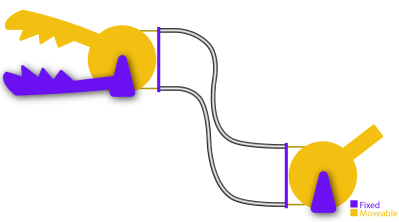
In this setup above, we can still control the Chomper remotely through the joystick and the mechanical control cables, albeit, with some added friction. Ideally, the conduits routing the cable are extremely flexible and do not compress when a compressive force is applied to them. That might sound like sort of magic component–but it’s not! It’s actually just a long skinny extension spring like these parts from DR Templeman. These parts go by a few names: continuous-length extension spring, spring guide… but I’ll generally refer to them as spring guide when referring to them in animatronics projects. This spring guide is extremely flexible, but also resistant to being compressed since it’s made from stainless steel.
If the above example seems a bit far-fetched, take the braking system on your bicycle as an example of a cable-actuated setup. Here, your hand squeezes the brakes on one end of the bike, which moves a length of cable running through a sheath on your bike, which moves your brake calipers and eventually squeezes the rim of your wheel hub to slow you down. Instead of a second conduit, however, an extension spring provides the return force to open the brake calipers when we release the handle.
All in all, these mechanisms really shine in situations requiring tight clearances, backlash-free control, and a limited angle of rotation. Properly designed, cable drives can be made to be both backlash free and back-drivable. But they’re no miracle elixir here. They have limits, and the capstan equation is fundamental to understanding your biggest challenge when it comes to their design: friction.
You vs. Friction: Conduit Edition
Wouldn’t it be neat if we could control anything remotely, using mechanical control cables from a distance? I totally agree! But it’s worth asking, what’s preventing us from weaving our cable and conduit in and out of some arbitrary setup? The answer comes down to friction. Friction is our enemy here, putting a limit to how much we can physically bend the conduit before it becomes too difficult to move. But the specific relationship to our problem is rather unintuitive! To build up a rigorous understanding of how friction affects the cable, let’s start by working a sample problem.
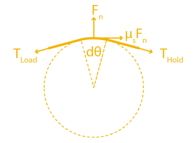
Let’s get rid of the conduit for a minute and start with a crude model using just two ingredients: a cable and a cylinder. In the image below, we’ve wrapped the cable partially around a fixed cylinder, and we’ve put both ends of the cable in tension so that the cable hugs the cylinder. Keep in mind that the cylinder can’t rotate, so if we wanted to move the cable, we’d have to fight friction here and rub up against the cylinder.
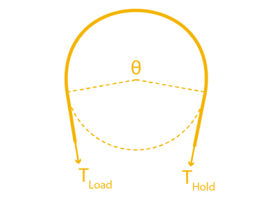 Now let’s start by putting both sides in tension with two tension values: TLoad and THold. We’ll keep the tension constant on THold, but let’s slowly increase value of TLoad. If our cylinder were actually frictionless pulley, trying to create a mismatch in tension would be impossible; the tension on one side would always be equal to the tension on the other side. But because our cylinder is fixed, it is, in fact, possible to increase the tension on one side while keeping the tension on the other side constant, all while the rope doesn’t slip in the process. This happens because static friction on the cylinder is acting against the tension increase up to a certain limit.
If we zoom in on a cross section of rope to examine the forces acting on a small sliver, we can see how static friction is acting against TLoad, which is equalizing the tension mismatch so that the cable doesn’t slip.
So here’s the big question: for a fixed value of THold on one side of the cylinder, just how much am I allowed to increase the TLoad on the other side before the cable slips and starts rubbing on the cylinder? (Heads-up! The full derivation requires some calculus and differential equation knowledge, but, for the curious, have a look at this PDF.)
TL;DR: the answer is the Capstan Equation. It tells us that, for a given holding tension on one side, the maximum amount of tension we can put on the other side of the cable without slipping is given by:

Moving both T’s over to one side gives us something a little more interesting: a ratio between two tensions.
Let’s have a look at this equation’s inputs. µs is the cable’s coefficient of static friction, a material property that we can look up in a table or material datasheet. θ is the total bend angle between your two tension vectors, TLoad. and THold, measured in radians. TL and TH are the magnitudes of each respective tension value.
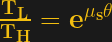
Also, an important side note: the bend angle θ is cumulative. In other words, if you add another fixed cylinder into the mix, you have to add up the total bend angle there too. That’s true even if the angle bends in the opposite direction as shown below:
So the total angle that we’d put in the capstan equation is given by θ1+ θ2.
What’s key here is that only two properties, bend angle and coefficient of static friction, will dictate just how much extra tension we can add on one side before the whole setup slips. So what can we glean from this equation?
The first key takeaway is that the cylinder size has no effect on the amount of friction mismatch. In other words, a small radius cylinder will produce the same resulting value that a large radius cylinder would, provided that the overall bend angles are the same. That’s not intuitive! I should mention, though: the equation above assumes that the cable is infinitely flimsy, which is a good approximation unless our bending radius is really small, like a few multiples of the cable diameter. In that case, the force required to bend the cable does matter. But, for most situations, we can ignore it.
Another key takeaway is that the relationship is exponentially related to the bend angle! So while one wrap around the cylinder might not add much friction, adding a second wrap more-than-doubles the maximum tension ratio between the two cable ends. For an example, with a cable who’s µs = 0.3, two wraps is 6.6 times more friction than one wrap. Three wraps is 43.4 times more friction than one wrap [math link]. But if our µs = 0.2, than three wraps is only 12.3 times as much friction as one wrap. In short, exponential relationships are not intuitive and add up quickly, and picking a cable with a coefficient of friction that’s as small as possible (like this nylon-coated cable) is key to keeping the excess friction low.
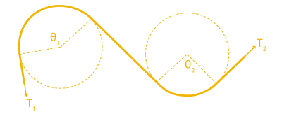
On its own, this example feels pretty obtuse, so let’s tie it back to our original problem with our cable-driven chomper using conduits. To translate the takeaways from problem to our setup, we simply substitute the cylinders above with conduit, and–voila–the exact same equation applies to this setup also! Since both the cylinder and the conduit are fixed, the capstan equation applies to this situation too. Here the cumulative bend angle is coming from the total bend of the cable that’s in tension.
Notice that I only marked angles θ1 and θ2 on one conduit, not both. That’s on purpose. For a clockwise torque applied to the joystick, only one cable is being put in tension; the other one goes slack. In other words, only the bends on the cable in tension add to the friction cost. If we applied a torque on the handle in the other direction, the friction costs would come from the bends in the other conduit. In practice, we’d probably route both of these conduits together as a single bundle, but it’s important to realize exactly who’s responsible for the friction depending on the direction of the input.
Designing Around Friction Costs
Applied to our Chomper setup, the Capstan Equation tells us just how much harder we have to tug on one side of the cable before we can get the other side of the cable to start moving. If we know the our cable’s coefficient of static friction and can estimate the max bend angle of our setup, we can estimate the maximum tension value our setup will ever encounter, which, in turn, helps us spec a motor with the appropriate amount of torque.
But there’s another, even simpler takeaway from this equation that we can use as a general rule of thumb. When it comes to designing your own cable driven mechanisms that use conduit, we want to remove any unnecessary bends anywhere else in the cable. In other words, conduits aren’t a catch-all solution for routing a pull force anywhere else in our system. Every bend that we add to them adds a friction cost, and that added friction can be computed with the capstan equation.
Now that we know how friction and bend angle are related, how could I adjust my design to reduce some of the unnecessary friction that the motors will need to fight through? (I confess that I didn’t know the capstan equation when I made this setup.)


If your system needs to route cable through a host of bends, consider introducing pulleys to do some of these bends for you. Since pulleys roll freely, they don’t add friction, and, therefore, do not contribute to the cumulative bend angle in the capstan equation.
A Teaser: The Inverse Problem
While the Capstan Equation is a huge bummer for preventing us from endlessly weaving our conduit through hard-to-reach sections of our design, a few cases exist where that friction is extremely useful. Since the tension on one side is exponentially related to the tension on the opposite side, with only about four wraps, we can actually use the capstan cylinder to drive the cable directly without worrying about the wire slipping.
This marvelous property gives way to a mechanism called a capstan drive, a cable wrapped around a small shaft that can be used as an actuator. Here, we’ve put the Capstan Equation to work. We’re counting on that exponential relationship so that our cable doesn’t slip while the cylinder is rotated. These mechanisms are just too cool to gloss over, so we’ll revisit them in a future post. Until then, we hope this brief intro helps you think a bit more carefully about routing cables in your next push-pull cable conduit project, tentacles included or not.


Due to their backdrivability and low/no backlash, capstan drives are great for devices with haptic feedback. I remember working with a 3D demo of a haptic pen powered by a capstan drive, where you could “feel” computer-generated textured surfaces displayed on the screen.
Bravo, Joshua! I hope you get paid extra for this!
Wonder if combined with something like Nitinol for course/fine movement?
https://www.chemistrylearner.com/nitinol.html
There should be similar math/physics involved in wrapping belts around pulleys, even though we don’t generally care about friction between the belt and the pulley. For example, I have noticed that in a corexy mechanism it takes a lot more force to move the carriage along the X axis than to move in the Y direction. If you use the minimal pulley arrangement, moving in Y requires the belts to bend and move around just the 4 corner pulleys, and moving in X requires bending and moving the belt over all 8 pulleys (plus drive pulleys, of course). I’ve seen people using different belt layouts where they throw in extra pulleys (to tension the belts, or provide mechanical clearance) and wonder if their motors are able to drive the mechanism with the added load that creates. Steel core belts require a lot more force to bend around the pulleys than glass core belts. Every pulley adds friction (bearings in the pulley), rotating mass, and extra force to bend the belt(s).
[mrehorst] said: “There should be similar math/physics involved in wrapping belts around pulleys, even though we don’t generally care about friction between the belt and the pulley.”
Actually, what’s being discussed here applies equally to belts and pulleys. Exerpting from [1]: “The capstan equation or belt friction equation, also known as Eytelwein’s formula (after Johann Albert Eytelwein), relates the hold-force to the load-force if a flexible line is wound around a cylinder (a bollard, a winch or a capstan).”
[mrehorst] said: “…even though we don’t generally care about friction between the belt and the pulley.”
We should always care about friction between the belt and the pulley. If the tension on a belt is too low the belt will slip and eventually fail due to wear. If the belt tension is too high the shaft bearings connected to the pulleys will fail prematurely.
[mrehorst] said: “For example, I have noticed that in a corexy mechanism it takes a lot more force to move the carriage along the X axis than to move in the Y direction. If you use the minimal pulley arrangement, moving in Y requires the belts to bend and move around just the 4 corner pulleys, and moving in X requires bending and moving the belt over all 8 pulleys (plus drive pulleys, of course).”
I think you mean a “CoreXY” mechanism. See [2] for a good visualization of the standard CoreXY reference mechanism with ten pulleys (including one each on the two motors), complete with the equations of motion. Moving in the Y direction the belt for one motor moves over four of the five pulleys. Moving in the X direction the belt for one motor moves over all five pulleys. Assuming everything else is the same, that means it takes a little more effort to move in the X direction compared with the Y.
But everything else is not the same. Assuming the gravity unit vector is normal to the work plane, the carrier beam that spans the work space in the X direction will take more effort to move in the Y direction compared with moving the smaller and lighter rider in the X direction. In the end, will there be a significant difference in effort to move in one axis versus the other? I don’t think so, at least not in a properly designed CoreXY mechanism mounted with the gravity unit vector normal to the work plane. But if you mount the CoreXY mechanism on a wall with the beam horizontal along the X axis, it will take significantly more effort to move in the Y axis because you’re working against the pull of gravity.
* References:
1. Capstan Equation
https://en.wikipedia.org/wiki/Capstan_equation
2. core[X,Y]
https://corexy.com/theory.html
I would guess that modeling the efficiency loss is actually pretty hard–but that’s not to say that someone hasn’t done it!
Unlike the cable, the timing belt isn’t negligibly flimsy. Bending it deforms it internally, which costs energy, which would cut down on our overall efficiency from motor input end to carriage output end. Here the bend amount and the bend radius actually do matter! When we move in the x axis, we require bending the belt over four additional pulleys. Meanwhile, when we move in the Y axis, the crossbar moves as a single unit, so those pulleys don’t cut down on efficiency since we’re not doing any additional deformation; it’s as if they’re not there. (Of course, getting some hard numbers on this would probably be more satisfying, but how I’ve sussed this out for myself.) Hope this make sense!
Both bicycles and R/C models use low-friction cabling that can be tortured quite a bit before they start to bind. The nylon pushrods (push/pull) for models and “Jagwire” for bikes (pull onlly) are pretty good examples. These are also used in animatronics/SFX builds. Perhaps for a future article?
I should add that “Jagwire” is a product trademark and there are plenty of other competitors out there.
I had to look that up, a brand of Bowden cable. With stainless steel core, cool. The word usually is a mispronunciation of a large spotted cat or a British high class car.
One nice thing about bike cable is you can buy the housing in bulk. It’s harder to find very long lugged cable, but tandem cable is usually about 3 meters long. If you’re supplying the ends, you can find bulk cable, too, but bike cable has a variety of swaged ends that can be very convenient for use. It also comes in a variety of cable widths, and it’s worth matching the cable to the housing. (Shifter cable is significantly narrower than road bike brake cable, which is narrower than mountain bike brake cable.)
For brakes, the housing is made of spiral square steel wire, and can stand up to quite a lot of compressive force but does change length somewhat under heavy loads. For shifters, the housing is made of lots of high carbon steel wire twisted together, like a hollow rope, which maintains its length extremely well but can’t stand up to a lot of compressive force. So that gives you a tradeoff between strong pulls and precise movement.
There are also some weird fancy housings. Jagwire used to make one that was composed of loc-line style aluminum segments, so it was extremely light, flexible, and had tolerable compressive strength. I’ve known weight weenies to use plastic hydraulic line as their cable housing.
Cut brake line with an abrasive cutoff wheel. Cutting it with dykes smooshes it and all the wire sections fray out and are very difficult to get realigned to the point where it can fit through the housing. Abrasively cutting it on an angle makes threading it through the housing much easier.
Similarly, cut the housing with an abrasive cutoff. Most housings have a teflon or polyethylene liner for reduced friction and to prevent metal on metal contact and corrosion. If you can cut through pretty fast you’ll be okay but if you dwell long you’ll melt the liner and it’ll seal closed. You can use a sub-1mm drillbit or ice pick to poke through this to get the cable through.
There are specialized cutters for both cable and housing, and they work great, but it’s hard to justify if you don’t do a lot of work with cabling.
Use powdered graphite as lubricant. It doesn’t collect dust and clog up the ends, where they enter/exit the cable housing.
I gotta try a differential chain hoist arrangement with capstan drive, maybe a couple more turns for luck though if I make it heavy duty :-D
I found out I’m trying to reinvent the Chinese windlass. :-D Still an interesting principle to screw with though. Gotta try some adjustable height shelves or something.
Another example of how the capstan equation can be helpful:
When putting a knot at the end of a HDPE rope, to terminate it using a hole, this can decrease the breaking strain to something in the region of 50% of rated. By wrapping the rope around a curve before terminating, the breaking strain can be restored back to rated value.
(Why HDPE? Lighter than steel rope and zero creep variants are available)
I wish I’d known about the Capstan equation when I designed my tentacle (https://hackaday.com/2020/09/15/a-tentacle-thats-a-work-of-art/). It would have made me change some of the design parameters. The way I made it with the conduit spiraling around the arm and the same 90 degrees between the motor and the arm would have been designed out. The motor needed to much more powerful only to compensate the extra friction.
This was a good introduction into cable paths and how to optimize them
I wish you’d give full explanation to the original use of this term, the capstan itself. The rotating cylinder used to pull heavy loads via a rope wrapped around it, lifting ship’s anchors and moving stone blocks and so on. Still relevant today; many modern sailing vessels have electrically-powered capstan winches for rigging, and a portable gasoline-powered capstan winch is a great tool for small-scale backcountry logging and construction.
I think he’s going there in the next installment. Hang on tight.
Gotta say I really loved this article, and the nice deep, but approachable dive into math it took.
This is excellent technical writing and explaination worthy of a teacher covering this, if there were something like a school for applied maker skills (no, I don’t mean as technical as engineering degrees).
A good use I’ve seen of cables before was opening dust gates on full shop dust collection systems, and seeing how it can be both driven and drive without breaking here was really useful.
There’s a large amount of people smart enough to make use of the non-calc math defined here at the end to do some really cool projects who aren’t looking to do calc for much- thank you so much for taking the time to write this so well, I hope this will be expanded to cover nitinol shape memory wire applications in perhaps another installment.
Tape recorders are an interesting application of the capstan as well.
In the early ’60s I took a course in Statics. The instructor introduced us to the hitching post problem. He asked did you ever wonder why the cowboy on his way into the saloon so casually threw the reigns of his horse over the hitching post. He then derived the capstan equation.
I always attributed that behavior to the horses being trained to “ground tie,” but I can see how that example would be an interesting segue into deriving the equation.