We know what you’re thinking. It’s a bad power supply, of course it was capacitors to blame. But even if we all intuitively know at this point that bad caps are almost always the culprit when a PSU gives up the ghost, it’s not always easy to figure out which one is to blame. Which is why this deep dive into a failed ETK450AWT by [eigma] is worth a look.
The first sign of trouble was when the computer would unexpectedly reboot with nothing in the system logs to indicate a problem. Eventually, [eigma] noticed a restart before the operating system even loaded, which confirmed the hardware was to blame. A quick look at the PSU output with a voltmeter showed things weren’t too far out of spec, but putting an oscilloscope on the 12 V line uncovered a nasty waveform that demanded further investigation.
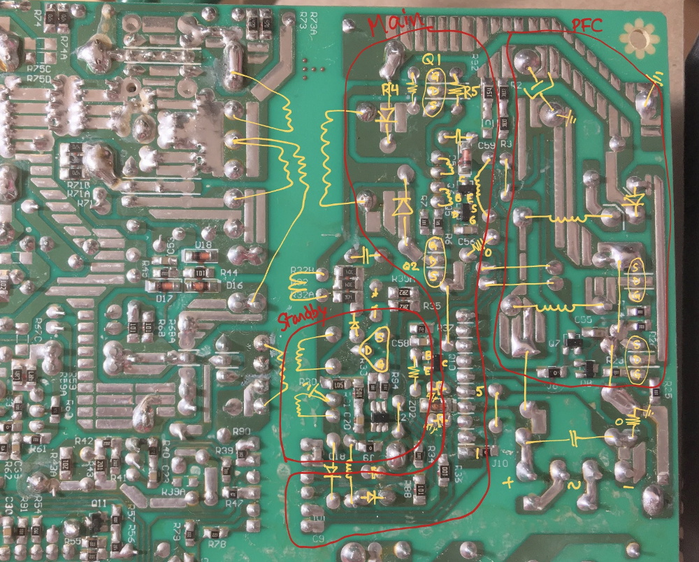
By carefully following traces and comparing with common PSU diagrams, [eigma] was able to identify the SG5616 IC that checks the various voltages being produced by the PSU and generates the PWR_OK signal which tells the motherboard that everything is working normally. As before, all of the DC voltages at this chip seemed reasonable enough, but the pin that was measuring AC voltage from the transformer was showing the same ripple visible on the 12 VDC line.
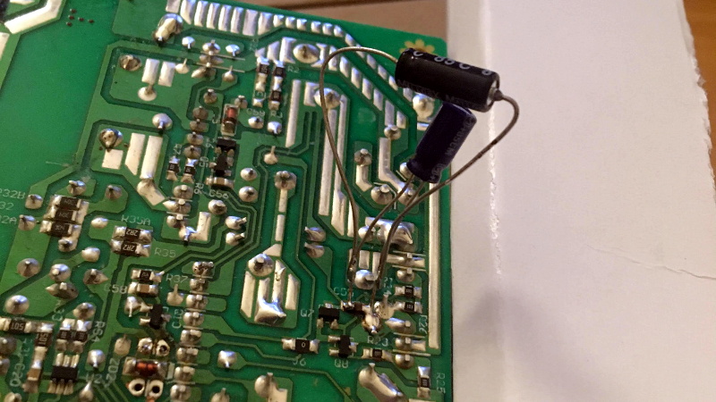
Even more digging uncovered that the transformer itself had a control IC nestled away. The 13 VDC required by this chip to operate is pulled off the standby transformer by way of a Zener diode and a couple capacitors, but as [eigma] soon found, the circuit was producing another nasty ripple. Throwing a few new capacitors into the mix smoothed things out and got the PSU to kick on, but that’s not quite the end of the story.
Pulling the capacitors from the board and checking their values with the meter, [eigma] found they too appeared to be within reasonable enough limits. They even looked in good shape physically. But with the help of a signal generator, he was able to determine their equivalent series resistance (ESR) was way too high. Case closed.
While swapping out blown capacitors in older electronics is something of a rite of passage for hardware hackers, this case is an excellent example of how even the simplest of fixes can be tricky to troubleshoot.


rite of passage
Quite
riteright. Fixed!Good tips, gonna have to bookmark and brainmark this for digging into my old Goldstar GS-520 which won’t do more than show me a green power connected light. Think it’s a PSU (internal) problem, as I get no screen light up and no floppy light flash.
Semi-update.. A few pcs of DC-DC buck convertors are hopefully turning up in the mail this week and if it gives me any more crap, the power board is coming out and two of those getting bodged in. (5V and 12V from 18V input)
A simple capacitor ESR meter like this may help to identify bad caps in circuit without having to desolder them. Sorry, it is in Czech language, but the schematic diagram is international. One may buy a kit. I am NOT affiliated with mr. Zajic, but I like his kits and I built a handful of them.
http://www.zajic.cz/esr/esr_metr.pdf
http://www.zajic.cz/esr/esr.htm
Are we expected to write the ATtiny firmware ourselves? Or is there a place to download or buy it?
This looks like the same one in English with a link at the bottom for “a” firmware, not sure it’s necessarily the one in the Czech language version. https://www.zl2pd.com/ESRmeter.html
Whoops, sorry, it isn’t, saw similar case design and big chip little chip on the diagram, and they’re different.
The link have non-workng firmware download. :( At least it gives an explanation on how it works.
The open source transistor tester by Markus Frejek is supposed to have a ESR measurement, but I don’t trust the numbers.
https://hackaday.com/2015/04/24/review-transistor-tester/
You may write your firmware yourself. Or you may convince mr. Zajic to ship the kit to your location.
“They even looked in good shape physically.”
Looks is handy. Sense of smell is another.
A very good diag-nose-sys technique.
No One: ” I love the smell of blown caps in the morning”
great article. And it’s *rite* of passage, not ‘right’ of passage.
Yeah, write!
B^)
Unless it’s an apprentice piece then it’s a wright of passage :-D
I spent decades repairing consumer electronics including the transition from the linear PSU to the SMPSU.
In the early days we would repair SMPSUs in most things including PCs but later it just became to easy and cheap to swap out PC SMPSUs.
My tips:
Get a good ESR meter that will test Caps in-circuit. This is essential.
The output stage of most SMPSUs goes (series) diode – (parallel) capacitor – (series) inductor – (parallel) capacitor – output rail.
You will often first notice that the output caps have leaked and or have high ESR. This is quite often a symptom of the problem and not the problem itself. *Just* replacing these will often give a SMPSU a new lease of life but then fail in a shorter time than expected.
The most common problem is at the regulation (PWM) stage and the switching transistor drive.
Look for a low value cap(s) near the Switch mode IC. It is most often 1uF/50V or 0.68uF/50. ESR test it. If it is high ESR then replace it with a 0.68uF/1uF 63V low ESR cap. Even if it is good replace it. It’s the most common failure.
If it is high ESR then the output caps will most likely need replacing too. Test them independently anyway. Where possible use low ESR here to, but that is not always possible as low ESR generally only go up to 1800uF. This is why you will see in well designed SMPSUs that there are a number of lower value low ESR caps in parallel to make up the full value with ESRs that are not available (cheaply) for the full higher value. Choose a higher voltage rating than the originals if you have the PCB space for them.
The second common problem are the series bias resistor(s) on the base of the switching transistor. These are often in the order of 120kOhm to 470kOhm. You will often see discoloration of the PCB where these are mounted and also often dry solder joints. Replace these unless there is no board discoloration / no dry joints or they don’t test OK.
Depending on your climate and the environment the unit lives in (ie is it air conditioned), you will often have several dry joints. Start with the obvious ones then continue to the suspect ones and go a little further as some dry joints are simply not visible but PCB discoloration is a good sign to look for.
As a side note the most difficult SMPSU repair I had to do was on and old Telefunken glass tube TV.
I take my hat off to the designers but at the same time it was perfectly clear that ‘ease of repair’ was not high on their agenda.
So here’s how it worked.
The flyback transformer (LOPT) was also the SMPSU transformer so there was only one drive transistor for SMPSU and horizontal drive / LOPT.
The transistor was driven with mixed frequencies (a modulated drive) one was the horizontal line frequency of 15.625kHZ (PAL) the the other was the switch mode chopper frequency which I suspect was a harmonic of the horizontal line frequency up above 100kHZ and likely more towards 200kHz, though I did not test this.
The HV (LOPT) (about 18kV) output is not bothered by drive frequency as it is rectified and filtered (diode/cap tripler).
The horizontal deflection used L/C filters to filter out the higher switch mode chopper frequency.
A extra (isolated) secondary on the LOPT used L/C filtering to remove the horizontal line frequency leaving only the switch mode chopper frequency and from that derived the main power rail (96V) that in turn was the supply for the very same LOPT.
Because the LOPT was also the switch mode PSU transformer and supplied the drive voltage for itself the circuit had a very complex (soft) start circuit.
I mulled over how this circuit works, replacing parts here and there only to have replaced parts fail again. In the end I discovered that Telefunken had a repair kit for this model that consisted of about 20 parts. A kind of ‘this fixes everything’ kit. And no wonder!
Hats geknistert und gestunken war es wohl… (sorry, german only)
Thank you for this interesting comment.
Last left off thinking I’d invest in a MESR-100 or was reading the DE-5000 is even better for the price. Any suggestions?
I’ve been impressed with the LCR-T4’s performance for the price… albeit desoldering and testing out of circuit and with the spec range.
Thanks for this excellent writeup on… your overtime work?
I do repairs myself, and usually you’re off cheaper and faster by doing a full recap – from tube radios to computer mainboards. radios need a full realignment then. Another trick is to hide newer and usually smaller counterpart in the original case – this even works when you heat the old tar capacitors up and pull the stuff out. modern cap will fit in easily.
i did this in quantity though i knew common failures on the pcs which were about the size of a cd-rom drive and only 1 cap would have done the trick. just to wait another week for the next one to fail and return to the workshop? you might know about the quality of electrolytics at these times.
I ended up having a pre-order list for all and after desoldering giving the multilayer a 0.7mm drilling so the caps fit in. And multilayer soldering needs POWER (notabene).
i ended up with an about 90% repair quote – all devices were out of warranty.
i still use a secondary monitor i got from leasing returns. (they usually die after 3 years leasing term for some reason… ;) ). put quality parts in and they last an eternity.
repairs are coming back. good for the technicians and the economy.
keep hacking! :)
Thanks for the TIPs, PAL (Telefunken pun intended).
I remember an article about the telefunken pop color TV from an old technical magazine (Antenna). Tricky problem because the culprit was on another section of the TV.
A bad filter capacitor from horizontal circuitry allowed some spikes to reach the the vertical stage transistors causing instantly burn (V > Vceo and subsequent damage to die).
At the time the advice was the same, use a new capacitor with higher voltage rating , as we did not have low esr caps to buy in early 80’s.
> Get a good ESR meter that will test Caps in-circuit. This is essential.
What would you recommend ? To much discussion around the subject to make a good purchase decision.
Not OP, but this https://ludens.cl/Electron/esr/esr.html looks good to me and is in my projects list (if i can find an appropriate analog meter). Testing Voltage is low enough so that PN-junctions do not conduct.
Thanks. Does it works in circuit ?
I found a 19 inch Acer monitor, and it worked, except if left on and connected to a computer, with time the Acer logo would appear. The monitor sure seemed to be resetting.
Once open, the monitor electronics was on a small board, the power supply on another small board. Easy to unplug and remove.
Nothing looked bad, but the resetting to me suggested the output voltage wasn’t right. It was easy to find the output electrolytics, larger values, I never got around to doing any circuit tracing. At that time, it was easiest to just replace 4 or 5 electrolytics. I could go further if it didn’t fix the problem.
It was a risk, but I just pulled replacement electrolytics off other boards (I don’t suggest that for others)
The monitor worked, and has never had a problem in four years.
Monitors are a bit different, since the power supplies vary, in size but also maybe voltages. So you can’t make a swap with a spare supply. If tye electrolytics hadn’t fixed the problem (I had no ESR meter at the time), I might have given thought to wiring in some other supply.
I had one a bit like that, LCD, was powering off a couple of secs after turning it on… found my way into it, power board, 3 caps looking extra crispy… two of them I had, 3rd one, hmmm it seems to be across 12V and if I can read it right it’s a 25V part (Browned up) … all I got is a 16V one though, oh well I thinks, I’m SURE that’s only seeing 12V …. so put that in and power up **SPLUT** .. obviously not… maybe some killer ripple though.
I know you can kinda sorta get a clue if you’ve got ESR problems if you find a cap that’s safe to stick your finger on, and it’s running hot, or warmer than it should be since it’s only been powered on 30 secs. However, quite often everything is mounted vertical and there’s no room for digits or it gets your knuckles near some high voltage.
Nowadays we have cheap IR thermometers but since they have a 15 degree cone minimum, if board is spread out enough you can be certain it’s actually reading the cap you’re targeting, you could have put your finger on it.
Is that the one with a laser beam coming out?
yes, so you know the exact center of the large circle that your IR sensor is averaging.
THe LCR-T4 component meters are cheap (chinese clones abound from the usual places), identify a number of components, and do a reasonable job of testing caps in circuit (and show the capacitance & ESR). They have an open source firmware: https://www.mikrocontroller.net/svnbrowser/transistortester/Software/trunk/?view=tar
Interesting article.
The main thing that keeps me away from serious troubleshooting of switching PSUs is… no schematic. Yes they’re almost commodity and one can get to know them, but its still a crap shoot. Couple that with how cheaply many are built, and that most of us have spares… it hasn’t seemed worth it to do much more than just replace them.
Back in the day, my 4 year old $5000 plasma screen needed a replacement of all PSU wet caps after just a few years. After that it ran without any problems for more than a decade until its retirement (though its location in the house kept slipping as newer awesomer screen tech became available).
Same thing happened with a 7 year old “black box” in a Ford diesel. Swapping the wet caps saved a $1,000 trip to the cleaners and 8 years later the thing is still happy as a clam.
Bought a DVD-VHS combo in 05 and it popped it’s PSU caps 1 minute and 32 seconds after the warranty was out… well seemed like.. it sat around for a year maybe until I sighed and bought generic caps in RadioShack (Think it had just become TheSource here) which they had marked down (never to be seen again) so stuck those in it and it’s been chugging along fine, touch wood. Well the DVD decided to stop reading, though I am hearing that can be component drift in the laser feedback circuit, maybe that needs a cap. Still powers up and play tapes though… loudest frigging VCR you ever heard though, no belts, all gears, whines like an older car with straight cut reverse gears. Shut it in a cabinet while it’s playing so I can hear the damn movie LOL
“A quick look at the PSU output with a voltmeter showed things weren’t too far out of spec…”
You don’t need an oscope to spot ripple. Just switch your DMM to AC mode. On DC voltages, it should read really close to 0mV, but if you have nasty ripple, you’ll get significantly higher readings.
Thanks Bubba, that tip sounds really useful! I’m filing that away for future use..
Hi,
Trick from the attic…. Last century, when I was in a TV/VCR repair shop, the fastest way to find bad capacitors in PSU was with an hair dryer in one hand and freezer on the other : hot air to resurrect and cold to pinpoint the guilty one. To confirm : heating again with the tips of the Weller and another throw of freeze, et voila !