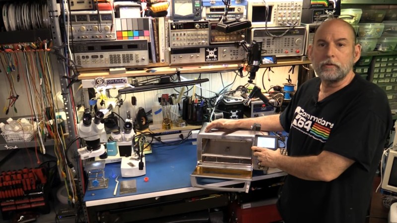
You can do your own Surface Mount Technology based PCB assembly with just a handful of tools and some patience. At the heart of my SMT process is stopping to inspect the various steps all while trying to maintain a bit of cleanliness in the process.
Surface mount or Surface Mount Technology (SMT) is the modern way to assemble Printed Circuit Boards (PCB) and is what is commonly seen when opening a modern piece of tech. It’s much smaller than the older Through-Hole (TH) technology where the component leads were inserted into holes in PCB, and act we called “stuffing” since we had to stuff the components into the holes.
A few specialized tools make this a lot easier, but resourceful hackers will be able to pull together a solder paste stencil jig, vacuum tweezers, and a modified toaster oven with a controller that can follow the reflow profile of the solder paste. Where you shouldn’t skimp is on the quality, age, and storage of the solder paste itself.
Join me after the break for my video overview of the process I use in my workshop, along with details of every step of my SMT assembly process.
Component Size Matters
Surface mount package names can be a little bit confusing. In the video I talk about pats that have a pin pitch of 0.5 millimeters, but when it comes to resistors, we use numbers like 0603 and 0402 which measure 0.06×0.03 inches. It’s always to good idea to have examples you can reference to ensure you’re using the right size package.
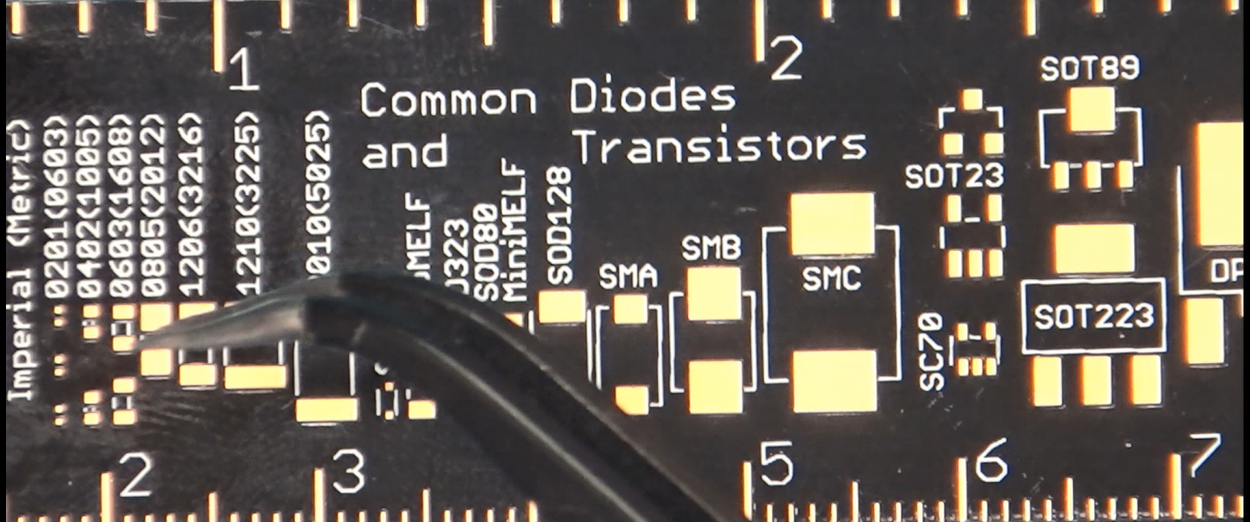
Looking at my trusty Adafruit ruler with component sizes shown I will say that I commonly do the 0603 size components on a regular basis, though I have done 0402 for RF components where less size means less things like inductance which fight you as you go up in frequency. I don’t work with the smaller 0201 components as I am afraid of inhaling them they are so small.
Pretty much all of the SOIC parts you see can be done using the methods I show in the video and I commonly go down to 0.5 mm lead spacing, though in the video I solder some chips which have 0.4 mm lead spacing, the smallest I do in my home lab.
Caring for Solder Paste
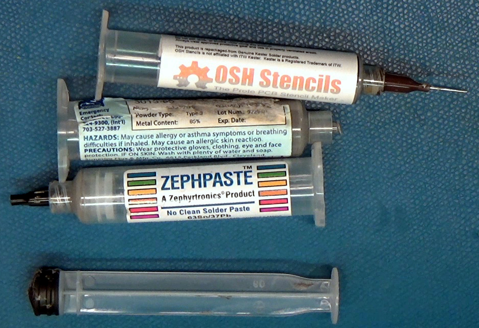
Nowadays we “place” a component on PCB’s without the need of holes for the components leads, and instead of applying solder after the fact in its molten form, we use a solder paste consisting of flux and solder. The paste can be packaged in a variety of ways but I buy my paste in syringes and I keep them in a small refrigerator and only for a limited amount of time as solder paste has a shelf life depending on the kind and where you buy it.
Solder paste is denoted by the flux that it is based on, I use “no clean” which means pretty much what it says, the end result is operable without cleaning the PCB. If I am delivering the board to someone else I typically clean it anyways which I go over in the video.
The solder is an amalgam of little beads of solder held in suspension with flux and can be the touchiest thing about DIY soldering as the solder has a definite shelf life of weeks if not days depending on the manufacturer. Simply put if you don’t remember when you purchased your solder, throw it away. I buy a solder formulated for better shelf life named Zeph paste which keeps longer than a production mix, and I store it in a small dedicated refrigerator (think six-pack cooler) and stored upright in syringes with the needle pointed down.
Solder also comes in many types, starting with leaded vs non-leaded and then variations depending on what kind of flux it contains. I use the “no clean” version which doesn’t have to be cleaned, or can be cleaned with alcohol instead of the stronger flux cleaners.
Applying the Solder
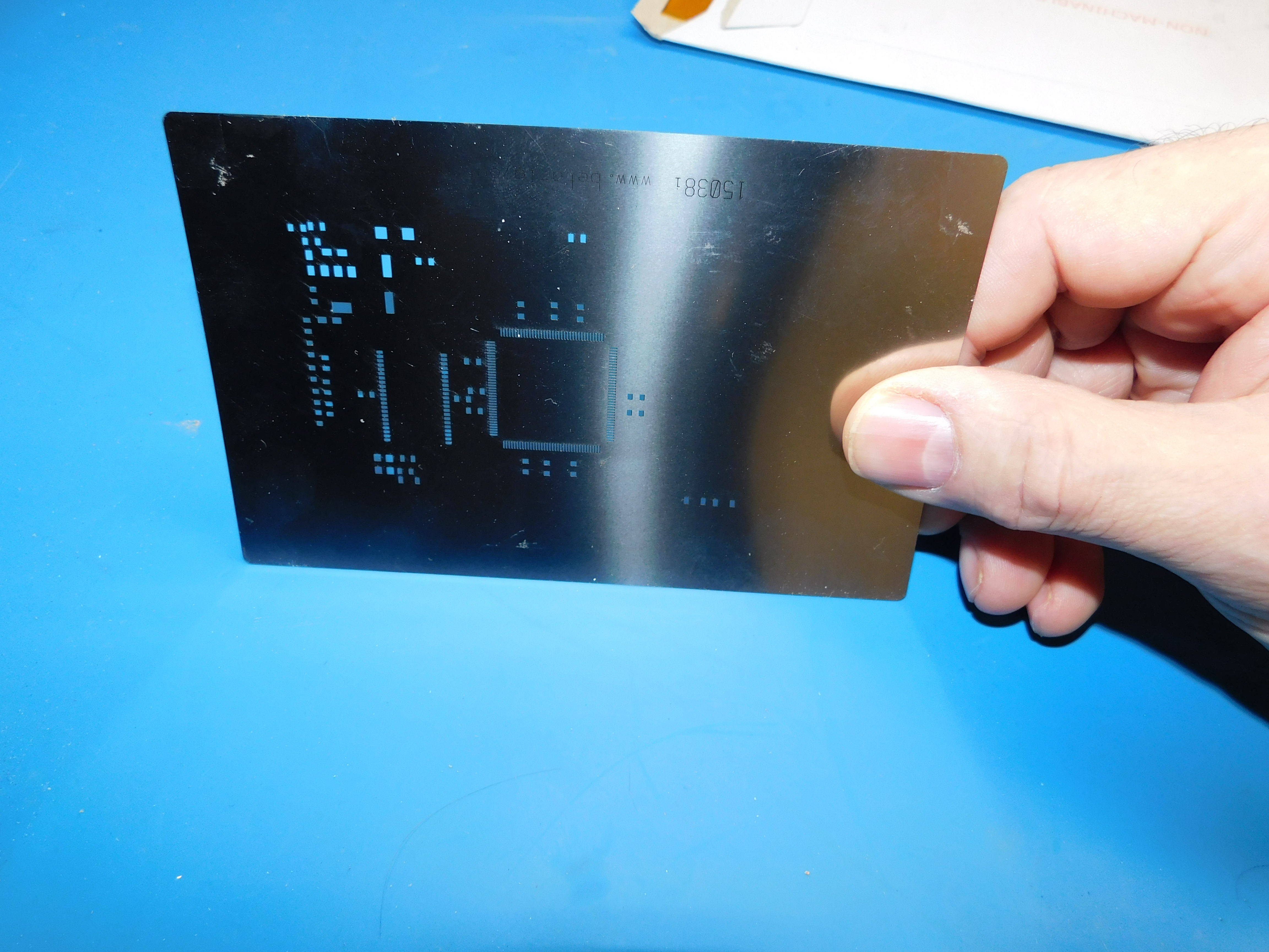
There are several ways to get the solder paste on the PCB; it can be manually applied using a syringe and good old fashion squeezing to deposit the solder onto the connector pads of the PCB. I also have an air pressure operated dispenser that I don’t really use.
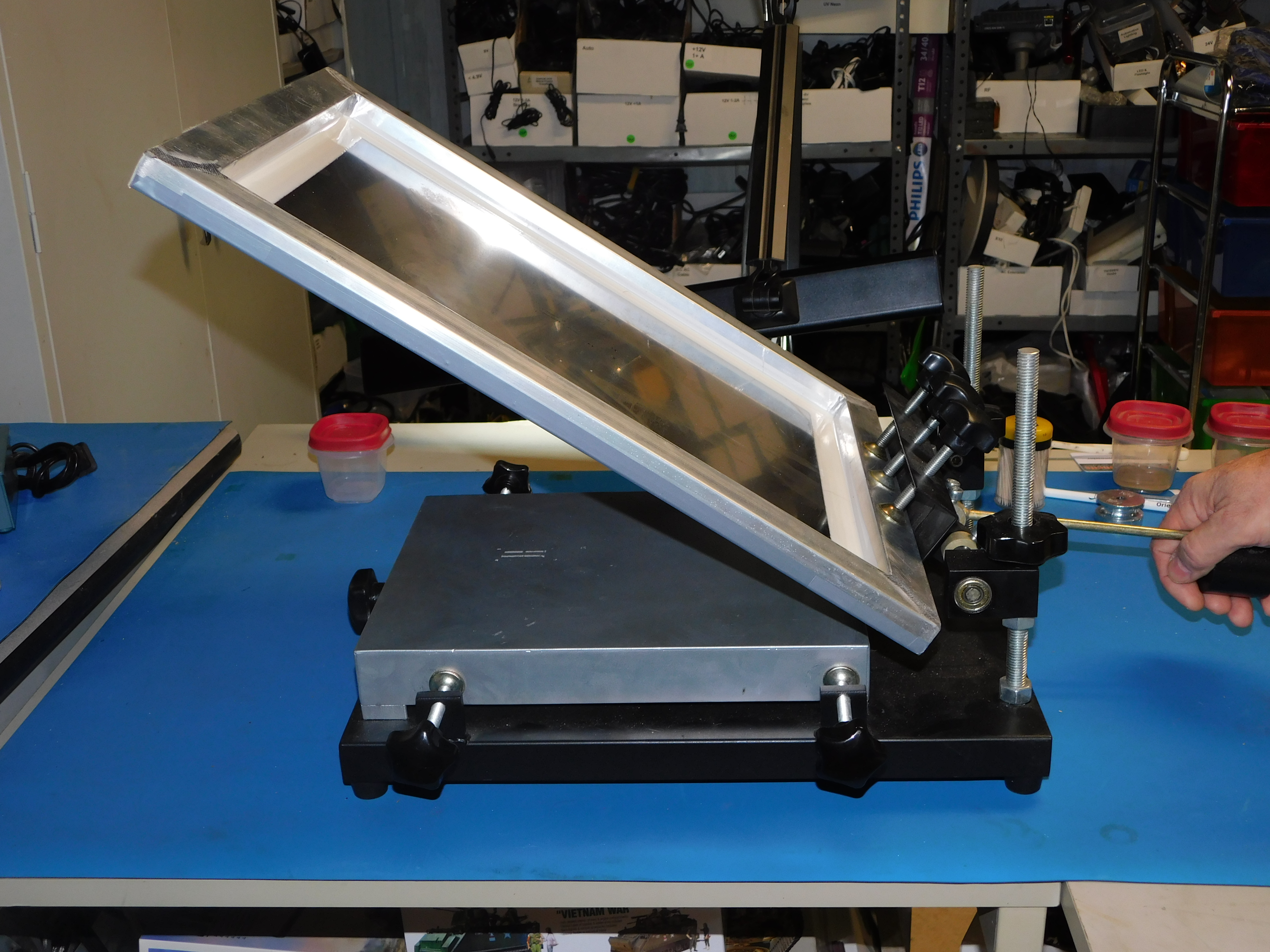
My go-to method is to use a paste mask stencil and squeegee the paste onto the PCB as seen in the video. There is a trick to squeegeeing the paste to not press too hard while forcing the paste through the paste mask screen. Paste mask stencils are available for a few dollars from the same sources I buy my PCB’s at, for larger runs I would look at companies like OSH Stencil.
Inspect Your Paste, then Place Components
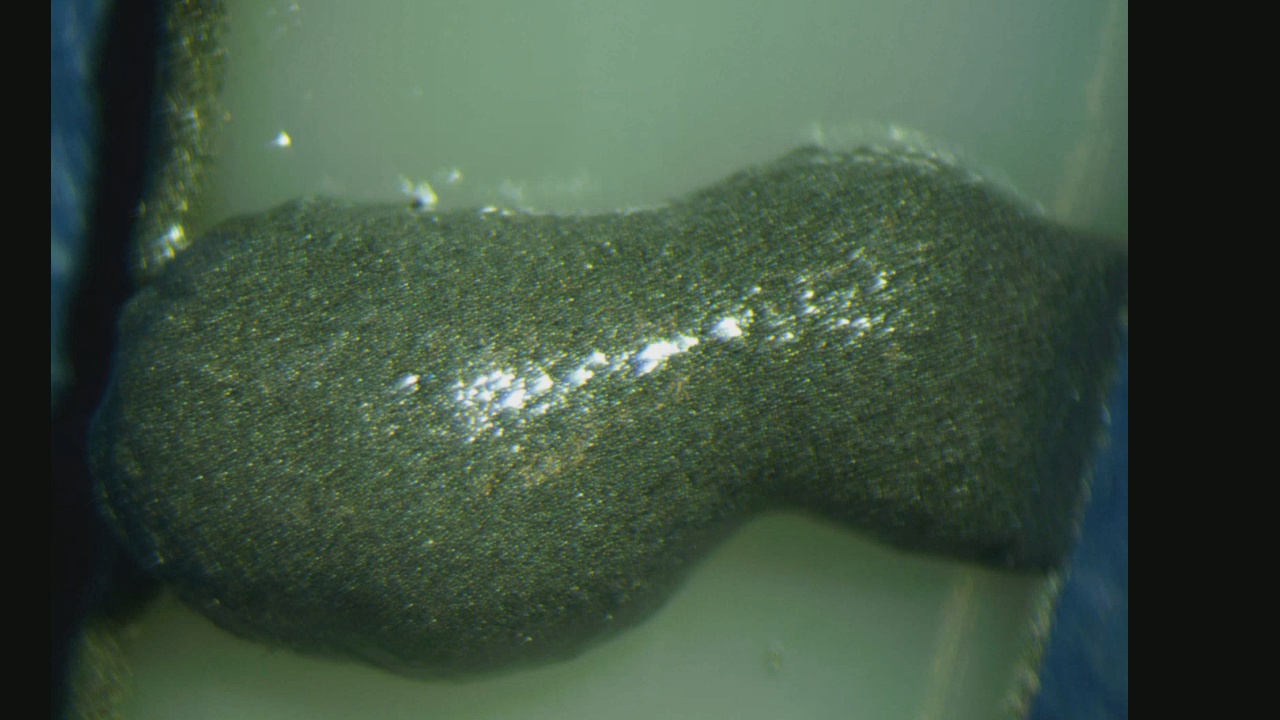
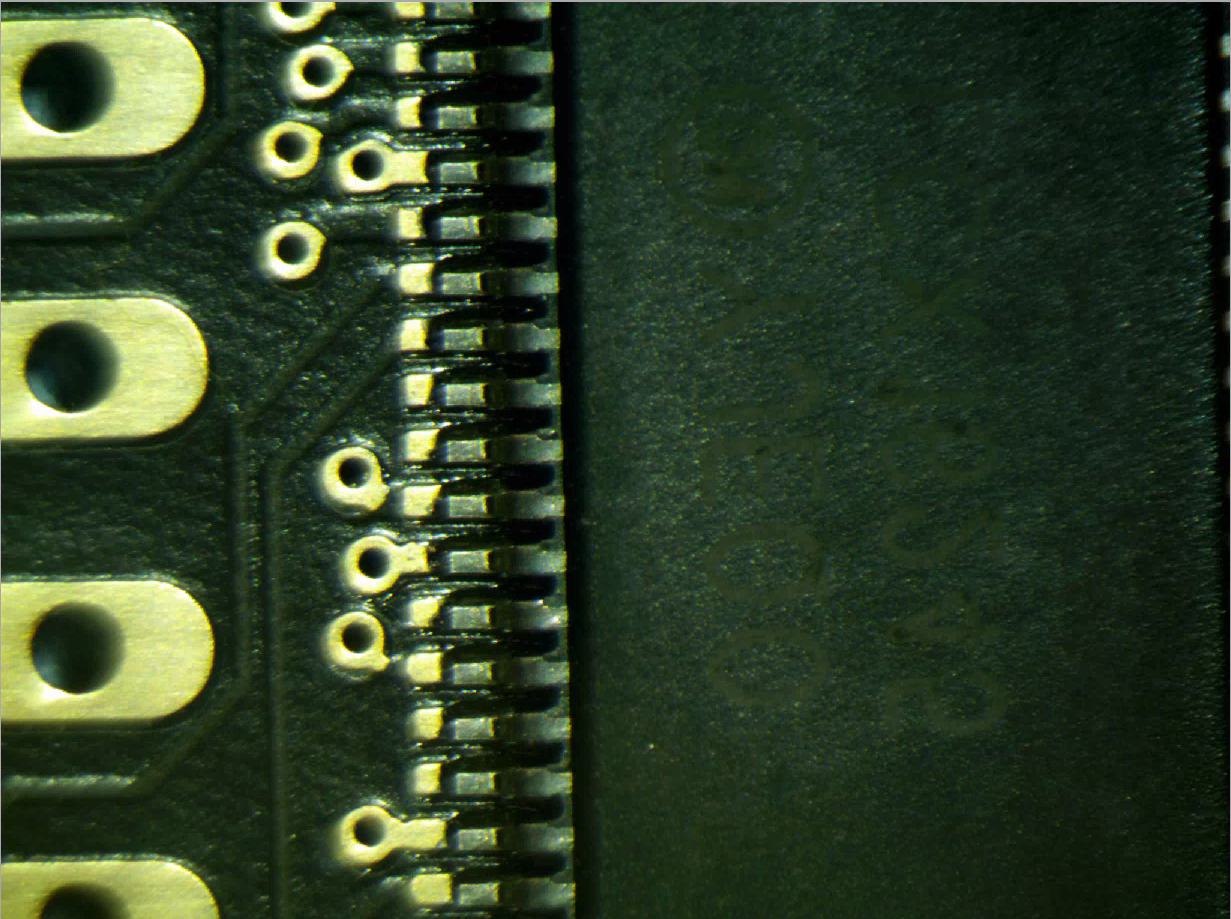
I always inspect the PCB before placing the components on the board and I use a stereo X10 microscope for this step. What I am looking for is anything that would create a solder short later, I.E. if its shorted now it will most likely be shorted later.
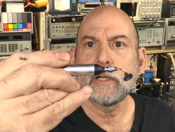
The trick is to place components on the board, kind of snuggled into the solder paste really, without smearing the paste or bending the component leads. Tweezers work for smaller components like resistors and capacitors but often for Integrated Circuits (ICs) one must be careful to lay the package flat. I have a variety of ways to do this using suction including the little suction cup with a squeeze bulb for a fully manual method or when doing a lot I might be inspired to fire up my little suction powered parts picker-upper made out of an old aquarium pump.
At Last, the Oven
I have tried a variety of reflow ovens including the T-962 (complete with mods per the Hackaday articles on the subject) but always found it wanting, especially with tall, dark components as the radiation patter inside the oven is somewhat uneven.
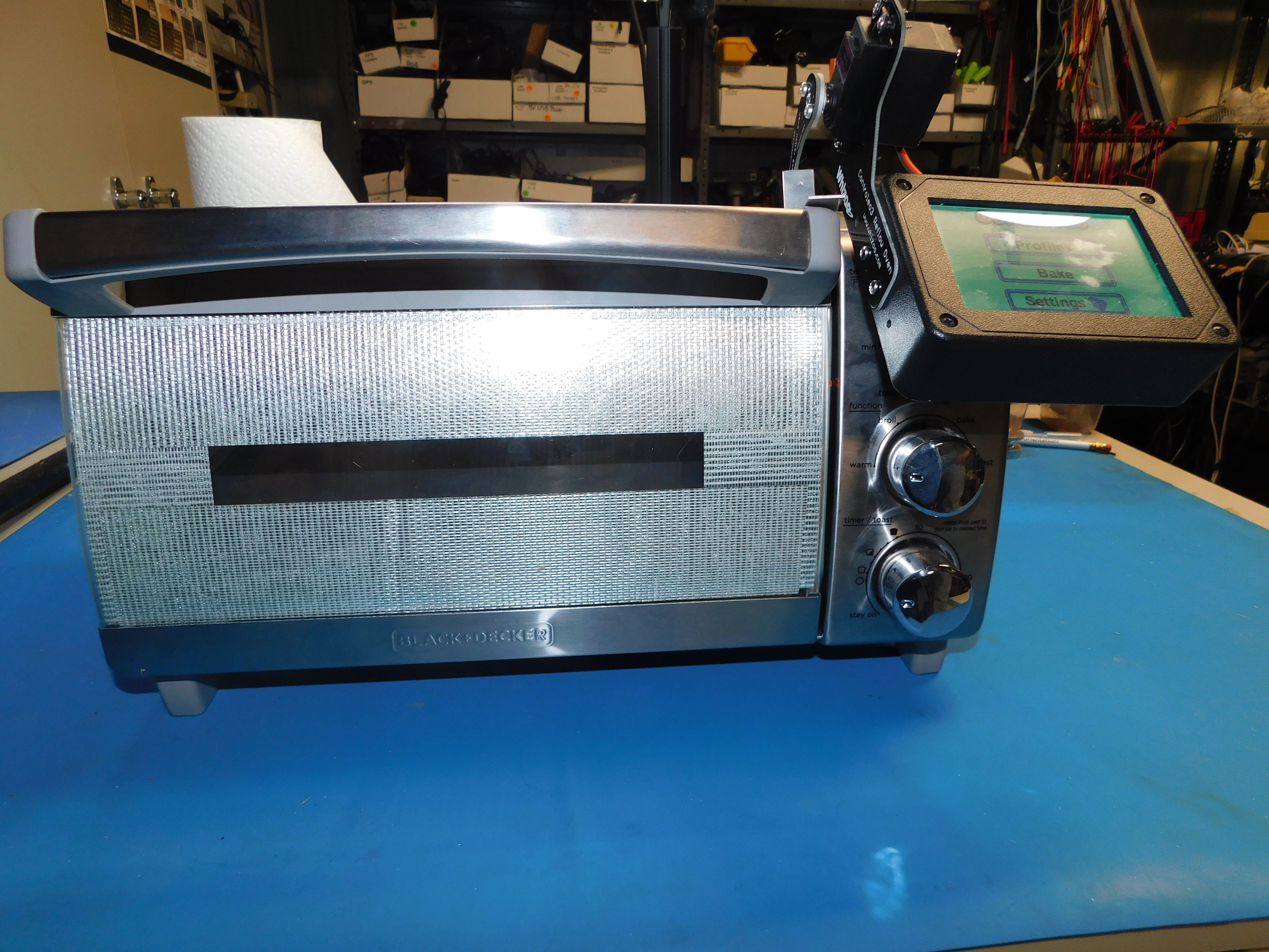
In order to make a better small scale oven I started with a Black & Decker convection oven and bought the Controleo3 oven controller which comes with an auxiliary heating element to boost performance. After applying lots of reflective tape and high temp RTV the oven is sealed against as much heat loss as feasible. The oven controller takes an hour for it to learn the oven’s characteristics but once learned I got really good and repeatable results.

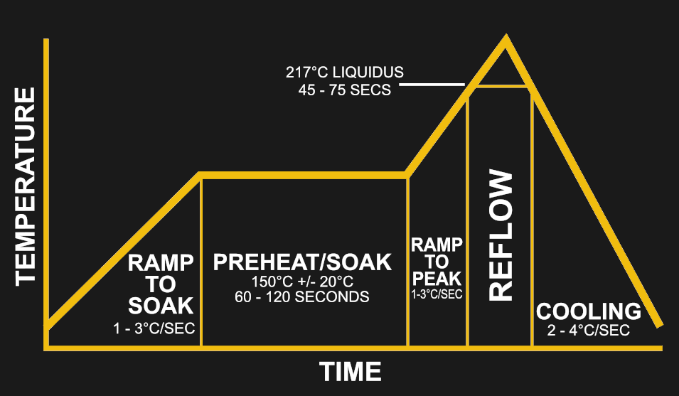
An important consideration is the Solder Profile which is a chart of heat vs. time. It is pretty much the opposite of just sticking the boards in a hot oven until the solder melts, which is pretty much guaranteed to just bake off the flux leaving little clumps of solder as opposed to the smooth reflow that we want to achieve. The Solder Profile takes care of various phases such as preheat and rapid cooling in addition to the actual reflow stage.
 I installed an additional heating element on my oven. The Controleo3 calibrates itself to the oven and even the size of what the oven is loaded with. I re-train the oven if doing large PCB’s using a blank board.
Final Inspection
True to my nature I slap the final soldered item under the microscope one last time and look carefully at each lead noting any solder bridges or voids in the process. I am also looking for the solder to have melted thoroughly and not look “grapey” or where the solder may have coalesced into tiny clumps instead of a properly whetted solder joint.
I like to give the boards a trip through my ultrasonic cleaner that I keep just for PCBs. While not usually necessary it gives the boards a nice professional look and makes inspection easier.
Conclusion
Hopefully one can see that doing DIY SMT assembly is certainly possible and can even be done for small scale production. In my case I can solder components down to 0.4mm lead pitch which is pretty small as long as I do ample inspection. Keep it clean, keep your solder paste fresh, and inspect at every step and you’ll get great results in your own workshop.


“Surface mount package names can be a little bit confusing.”
On a side note: This past year I saw “E” being used to designate electrolytic capacitors on the silk screen.
e.g. E243 instead of C243.
I’m not sure how the polarity was indicated though…
Thanks for the article Bil!
I had a bad experience with one brand of solder paste.
The solder balls were “too large” and when the flux melted they skittered off to and under components, some were the “perfect” size to get caught between the leads on other chips.
I’ve had the same and wish there was some manufacturer designation so I could tell the solder paste size without having to buy some.
There is a standard. A lot of solder paste is T3 solder ball size, but you can get finer (T4 & T5 would be even finer). I have noticed a handful of the solder pastes you can get from the usual suspects (Amazon, EBay, Aliexpress, etc) don’t seem to list that spec though.
There is designation. It is the mesh size. Common mesh sizes are 3 through 5 with 3 being the largest. Anything smaller than a #6 mesh you have to reflow in an inert environment i.e.nitrogen.
There is such classification:
Type 3 (25-45 µm)
Type 4 (20-38 µm)
Type 5 (15-25 µm)
For solder balls sizes
Whew. The stuff we had was more like 0.4mm in diameter: 10x any of these. I wonder if it was for some entirely different process.
“…and some patience.”
You had me right up until then.
“I am also looking for the solder to have melted thoroughly and not look “grapey” or where the solder may have coalesced into tiny clumps instead of a properly whetted solder joint.”
What do you do if you find errors? Throw it out and start over, reflow it, or can you spot fix things with a heat gun?
A lot of the time if it’s a small bridge or something it’s easier to throw some flux on the joint and fix it with an iron.
Solder wick on the bigger stuff. If you are quick you can eliminate the bridge and keep the other two joints soldered.
“Simply put if you don’t remember when you purchased your solder, throw it away.”
For pure reflow I totally agree, only use fresh paste. That’s what I do as well. Reflow depends on the flux+solder paste acting the way it’s supposed to.
However, I’d actually say – don’t throw away old paste! I’ve actually found you can use it perfectly fine in a syringe for hand soldering, either with an iron or a hot air gun. It goes “bad” because of the flux drying out: but if you’re using it for hand soldering, you can flux the area beforehand and drop the paste on it.
I’ve got a syringe that’s nearly a year old (guess how I know…), and it’s perfectly fine for hand use. Paste is helpful for hand soldering because you don’t have to hold the solder with your magic third hand.
In the video I try and explain that the regular ‘ole paste I have picked up in the past goes bad rather quickly, however I use a brand of paste that seems to survive the fridge fairly well.
The paste brand I typically use is ChipQuik’s SMD291AX10, which has a 6 mo unrefrigerated/12 mo refrigerated shelf life by the datasheet which is already pretty nice, but obviously I’m way past that point.
Like I said I can definitely tell that it’s aged and I wouldn’t want to shove it through a fixed reflow cycle, but it’s absolutely still totally usable.
Heck, a few months back I just finished off a syringe of that which was 4 years old, and it was still totally usable by hand. It’s really just the flux aging that’s the issue.
ChipQuick is just stellar, I wouldn’t use any other stuff
I have a syringe of solder paste around for hot-air rework and manual stuff like that. According to your logic, I don’t have to throw it away as I still remember when I bought it: somewhere in July of 2016. Still works like a charm for manual stuff, if it’s too hard I usually mix it with a bit of liquid flux and it’s good to go again. (To be fair, if I were to do a batch of PCBs or anything automated like your oven I would buy some new stuff.)
It’s not clear what goal your article addresses… but you can certainly “do SMT assembly” just fine with a soldering iron, solder wire, some flux, tweezers, and a magnifier of some sort. Best not done right after a coffee, but overall I find SMT assembly infinitely easier than through hole with it’s maddening flipping of the board and components that move around. I’d agree that below 0603 or 0.5mm pitch it becomes less fun…
Soldering iron on mlcc’s is always a terrible idea. So is any kind of btc’s. You can do the above with a hit air rework station but you lose control of the peak temps you parts will see. Anything outside of hobby/brassboard stuff just send it to a cm.
I’ve done a little small-scale assembly using a stencil for the paste, tweezers to place components, some as small as 0603, and a hot air rework station to make the paste shiny. I’ve found a stiff drink about an hour prior to assembly does a great job of steadying my hands.
I’m being serious; it worked for me. YMMV..
The limited shelf life of solder paste is why I’ve just avoided using the stuff for hand assembly. I’ve found that using solder wire with a flux pen on hand does the job well for me.
The limited shelf life’s really only an issue for fully automated reflow, since everything’s timed. I mean, the manufacturers give you a profile to follow – so obviously once you get out of that ‘shelf life’ that profile won’t work anymore. With hand soldering, paste can be super-old and it’s not a big deal – you just have to watch it.
I mean, with an actual soldering iron I’d be hard pressed to even notice the difference. With hot air you can definitely tell, but like I said it’s just a matter of watching until the solder hits liquidus, and being careful about the amount of air you deliver since the (remaining) flux activation’s a bit tricky.
To be clear, I’ve recently just soldered on a bunch (10) of QFN48 package parts using hot air and a syringe of ChipQuick SMD291AX10 that’s been out ~12 months unrefrigerated, plus buckets of 0603s using an iron. I maybe had to dress up a pin or two on the QFN48s with a bit of flux and touching it with a fine tip on the iron, but that’s it.
Thermally stable solder paste is great. I have had Chip Quik TS391SNL50 (15 EUR for a 50g can) on my shelf in room temperature for over two years now, and it still works well. If the flux starts to separate, just mix with a stick as specified in instructions and it’ll be fine again.
That Controleo3 is a neat thing to know about and worth the writeup on its own. It’s also good to know there are longer-life solder pastes; I’ve only ever hand-soldered smt precisely because the paste dies so fast.
By the way, Bil, it looks like you have a HP 3314A ARB on your bench. You might already know about the easter egg in it, but if not: hook up a speaker to the ARB output, and push shift-SW/TR-START FREQ at the same time as you power it up. (And be patient: it takes a long time to start.)
Was that your father’s easter egg? Mike pointed me at a comment several years ago about the egg.
Yeah, it was. I have several 3314’s in various stages of completion/functionality, including some prototypes. They’re great for their size.
Which liquid do you use with the ultrasonic cleaner? Water or Isopropanyl alcohol?
About the shelf life: If you are using a stencil anyway, it helps to buy the solder paste in a little pot (20g pot is plenty) instead of a syringe. If you keep sealing it carefully after use and store it in a fridge it easily holds up a few years. Mine is four or five years old now and it still reflows beautifully. Just some tape on top of the pot opening, screw on the lid tight and seal the lid from the outside again with another layer of tape.
I use a cleaner from sra-solder.com labeled “35” but was the result of some research at the time. I also have used DI water and a whetting agent but really like the 35.
Detergent 8 works well on removing flux, I imagine it would work fine in an ultrasonic (does list it can be used in ultrasonic cleaners.)
It is rather on the expensive side, but you can request a sample to try it out.
https://www.alconox.com/product/detergent-8
Solder paste will last many years if stored correctly. I bought a jar of unleaded solder many years ago – it expired many years ago too! (>5 years)
I keep it inside a sealed ziplock bag with as much air removed as possible. I decant some into a tiny sealed glass jar – an old sample sized jam jar, and again keep it in the fridge in a ziplock bag. This gets thrown out sometimes.
To rejuvenate, after extracting from the main jar (ie don’t rejuvenate the main jar), add a little 100% isopropyl alcohol (a few drops) and mix. Others have added flux instead. You need to get the right consistency, not too liquidy!
I have a $5K desktop commercial reflow oven. I make 10-20 pcbs at a time, using 0402, 0603, TQFP100 etc using stencils (ss and Mylar) without any problems.
This method works! I have a bottle of MG Chemicals halogen/rosin free liquid flux for this purpose. Some isopropyl alcohol can be used as well.
Fantastic article, Bil! Thanks for doing it. I’ve bookmarked it for future reference.
Just a note, Eurocircuits have something they call EC-registration. It’s a small jig that aligns you board and stencil. And you just tick it with your PCB order. Just need to buy the jig first time. I have had great success with it.
For low quantities of PCBs, why not just solder them with a soldering iron. I find it far easier and less messy to get good results that way, and you don’t have the extra expense of stencils and paste with a relatively short shelf life.
I do pretty much all my boards by hand, usually using 0603 passives, and .5mm tqfp packages for most things. Smaller is still plenty doable, but gets a bit too fiddly for my taste, so I usually only go smaller if there’s a good reason to.
I have a hot air station as well, though I rarely use it. Usually I only use it for removing ICs etc.
There’s nothing wrong with using an oven if you want to, or if you want to do BGA, etc, but I think a lot of beginners waste a lot of effort and money on toaster ovens, skillets, hot air, and solder paste to accomplish things that can easily be hand soldered with a small amount of practice.
You need a decent regulated iron that’s not too pointy (counter-intuitively), some decent solder, flux, tweezers, and probably some kind of magnification unless your eyes are good. I just use some moderately strong reading glasses.
Far less equipment required, and I find it much easier to get good results.
It’s good to be able to do both. For small boards, soldering everything manually certainly is an option, but for larger boards, solder paste and baking (or using a hot-air rework station) tends to be quicker and give nicer results. I tend to do both, it depends on the complexity of the board what method I choose (fully manual with a soldering iron, dispensing solder paste manually and hot-airing the components, or using a stencil and hot air to solder the components)
Are you sticking things down with tape or something? I use a soldering iron for touch-ups, but never for getting components to stay in place.
for small passives (0603 caps/resistors, etc), I’ll just lightly tin one of the pads on the pcb, then I’ll hold the part to be soldered flat against the board next to the pad with tweezers, touch the soldering iron to the small pillow of solder, and slide the part into place (onto the paholding the iron there just until I see the solder wet to the contact on the part. Even if it’s a really poor connection, as long as it’s actually stuck down with some metal, and not just flux, it’ll be fine. I then solder the other end of the part, mostly focusing on heating the pad, more than the component. When it wets, it should ideally have a smooth-ish fillet, though I admittedly usually add more solder than is ideal. I then go back and solder the first side again, to make sure it has a proper connection.
for ICs, generally I just flux the pads on the board, carefully align and hold the part in place with tweezers, or my finger. Wipe the tip of the iron to make sure it’s good and clean, add a tiny bit of solder to the tip, and then touch it to one of the corner pins. with the flux there it should pull the solder into the joint nicely. I then do another corner or two the same way, so the part is solidly attached, and then I solder the rest of the pins by just moving along and bumping my iron up against the ends of the pins 4 or so at a time, in sort of a modified “drag soldering” technique. You’re using flux and surface tension to pull the solder into the joints, so you actually want a fairly wide chisel tip iron.
Another important point is that it’s generally better to use a chisel tip, or at least a more blunt conical tip, especially if you’re using typical hobby-class equipment. (regulated, but not high end stuff with fancy heating/sensing)
Many people assume that you want a super fine sharp tip because you’re soldering tiny connections, but in reality, you’re relying on surface tension to get the solder in the right place and it’s important to get the connection quickly hot enough to wet, and then get off it.
Thin tips on basic irons don’t conduct heat well enough, so the tip cools off when you touch the joint, and then it takes much longer to get back up to temperature, and you’ll often boil off most of the flux, and get a more oxydized lumpy connection, which is also more likely to bridge pins on ICs etc.
Generally, if I had to choose one tip to work with, it’d be a chisel tip, around 2.5-4mm wide. you can do almost anything with that, turning it sideways and using the corner of it the rare time you do need something super fine.
With a really pointy tip, it might be easier with some of the smallest passives, but then soldering larger components and ICs is much more difficult.
Something not mentioned is that PCB design is important too, especially for small pitch components like QFNs. You very often need to shrink the stencil aperture size as it can be easy to get too much paste and get a bridge. Shrinking in the long dimension is of course preferable.
Note that you can cut stencils out of 4 mil mylar using a laser cutter. They don’t last forever, but I’ve easily gotten 20 boards out of mine.
Me: «It’s impossible to do SMD at hom–»
Bill Herds: «Hold my beer»
Great article, sir! :) Bookmarked as reference
My company employs tribes people with basic skills in the Highlands of VietNam for assembly work. We supply ‘kits’ for PCBs, which I personally delivered – so I knew the count was correct. I also knew how long it should take to assemble the PCBs since we supplied the SMD ovens..
Imagine my surprise when I was called a few days later with a message “Finished”. Curious, I flew up and sure enough the untested products were fully assembled.
I also found out they didn’t use the expensive oven we had supplied, rather they had bought a few basic smoothing irons (without steam, etc) and by inverting them had ‘cooked’ the PCBs a few at a time.
Never, ever, say you can’t learn from anyone!
P.S. Banggood.com are selling something similar: put 1776524 in product field!