Youngster’s ESP32 Jukebox Uses RFID To Queue Tunes

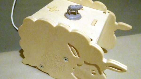
Though kids today have an incredible knack for figuring out modern phones and tablets, there’s still something to be said for offering a simple physical user interface for little hands. To that end, [Martin Hierholzer] has put together a whimsical jukebox that his two year old daughter can use to listen to her favorite songs. With just a few simple buttons, no display to read, and the ability to stop and start songs using RFID tags embedded into 3D printed figures, it’s a perfect interface for tiny humans just getting the hang of interacting with technology.

While the Raspberry Pi might have been the more obvious choice to base this project around, [Martin] decided to go the ESP32 route for improved energy efficiency. The popular microcontroller is more than powerful enough to play MP3s, and its integrated WiFi connectivity allows the player to download new tracks from the network occasionally. He added a micro SD slot to provide some mass storage, a PCM5102 I2S DAC with a PAM8403 amplifier to handle the audio side of things, and a MFRC522 RFID receiver that can pick up tags placed on the top of the player. Power is provided by parts salvaged from a USB battery bank, and everything is housed on a custom PCB.

The relatively low power requirements of the ESP32 means the jukebox can keep the party going for many hours (perhaps even days) when in active use. When the RFID token is removed and there are no songs to play, some clever coding kicks the chip into low-power mode to greatly extend the player’s standby time. [Martin] says it can sleep for months without having to be recharged, and considering some of the impressive feats of battery-sipping we’ve previously seen from the ESP32, we don’t doubt it.

Even if you don’t have any young music lovers at home, the documentation [Martin] has put together for this project is absolutely worth a look. Whether its how he configures the server side to push songs and firmware updates to the player, how he wrangled the ESP32’s Ultra-Low Power coprocessor (ULP), or the woodworking tips used to produce the charming enclosure, you’re sure to pick up a trick or two.

The children of hackers and makers always seem to get the coolest stuff, and we’re looking forward to seeing what [Martin] comes up with next. After all, kids grow up fast and pretty soon his daughter is going to need something new to entertain her.

Building A 60s Toy The Way It Should Have Been

The original Hasbro “Think-a-Tron”, a toy from the dawn of the computer revolution, was billed with the slogan, “It thinks! It answers! It remembers!” It, of course, did only one of these things, but that didn’t stop the marketers of the day from crushing the hopes and dreams of budding computer scientists and their eager parents just to make a few bucks. It’s not like we’re bitter or anything — just saying.

In an effort to right past wrongs, [Michael Gardi] rebuilt the 1960s “thinking machine” toy with modern components. The original may not have lived up to the hype, but at least did a decent job of evoking the room-filling computers of the day is a plastic cabinet with a dot-matrix-like display. The toy uses “punch-cards” with printed trivia questions that are inserted into the machine to be answered. A disk with punched holes spins between a light bulb and the display lenses, while a clever linkage mechanism reads the position of a notch in the edge of the card and stops the wheel to display the letter of the correct answer.

[Michael]’s update to the Think-aTron incorporates what would have qualified as extraterrestrial technology had it appeared in the 1960s. A 35-LED matrix with a 3D-printed diffuser and case form the display, with trivia questions and their answer as a QR code standing in for the punch-cards.He also added a pair of user consoles, so players can lock-in and answer before an ESP32-Cam reads the QR code and displays the answer on the LED matrix, after playing some suitable “thinking music” through a speaker.

As usual with [Michael]’s retrocomputing recreations, the level of detail here is fantastic. We especially like the custom buttons; controls like these seem to be one of his specialties judging by his slide switches and his motorized rotary switch.

Continue reading “Building A 60s Toy The Way It Should Have Been”

Arducam Now Working With The RPi Pico

The Raspberry Pi Pico came out of absolutely nowhere, and has taken the maker world by storm. At the low, low cost of $4, packing some seriously grunty original silicon, and even available free on the cover of magazines, it’s already got a legion of fans. As with any new popular platform, there’s a scramble to get everything under the sun running on the hardware. Already, ArduCAM is up and running on the Raspberry Pi Pico!

Based on the OV2640 image sensor, the ArduCAM is useful for microcontroller applications thanks to its onboard JPEG encoder. This limits the amount of RAM needed onboard the microcontroller to deal with the images fed from the camera. With the Pico now on the market, the team behind ArduCAM set about writing a library to get everything playing nicely with the SPI camera. It’s available on Github, complete with an example program so you can check everything is functional right out of the box. The easiest way to get up and running is from a Raspberry Pi environment, but the Pico acts as a USB Mass Storage device so can be programmed from virtually anywhere.

We’ll likely see the whole cavalcade of microcontroller bits and pieces ported to the Pico in the coming months, along with plenty of interesting uses of the special IO features. Video after the break.

Continue reading “Arducam Now Working With The RPi Pico”

AM/FM Radio Gets Bluetooth Upgrade

For many commercial broadcast radio has lost its luster, leaving an unknowable number of perfectly serviceable AM/FM radios to lie dormant. But they don’t have to. As [Dan Gebhardt] shows in his recent hack, integrating a Bluetooth audio receiver into portable radio may be easier than you think.

For this project, [Dan] wanted to make sure no original functionality was lost. The radio still functions on the AM/FM bands, but now with the flip of a switch, he can listen to the audio coming his way courtesy of a Apt-X low-latency Bluetooth receiver. It sounds like the link is quick enough that he can even use this as a wireless speaker for watching TV, which isn’t always possible with cheaper chipsets that introduce a noticeable lag.

Isolating the audio trace.

The trick was to track down the receiver IC, a Silicon Labs chip similar to ones we’ve seen used in a few DIY radio projects previously. A peek at the datasheet told him which pins were carrying the audio signal, and after following them around the board, he found a convenient spot to cut the trace before it went into the volume control. From there is was just a matter of wiring in a SPDT slide switch that allowed him to select which device was passed through to the radio’s audio hardware.

While he had everything apart, [Dan] exorcised the Apt-X’s original 300 mAh LiPo pouch and replaced it with a DC-DC converter connected to the radio’s battery compartment. This allows him to run all of the hardware off of the same set of rechargeable NiMH cells, and also provides considerably improved runtime for the Bluetooth receiver.

Now as for physically integrating the Apt-X into the case of the radio…well, what can we say? [Dan] admits it’s a bit rough, but then the point was never to enter the thing into beauty pageants. It works well enough for his purposes, and in the end that’s all that matters.

Building An Ultrasonic Levitation Rig

Levitation may sound like magic, but there are a wide variety of physical phenomena that can be manipulated to generate the desired effect. In this case, [Mirko Pavleski] has built a rig capable of levitating small, lightweight particles through the use of ultrasound.

The rig uses a 60W ultrasonic transducer, operating at approximately 40 KHz, to generate a standing wave in combination with a reflector – essentially a rigid piece of material off which sound waves can be bounced. The interaction between the sound waves as they are emitted from the transducer and bounce off the reflector creates what is known as a standing wave, wherein there are areas of high and low amplitude that do not move in space. These areas correspond to the wavelength of the emission from the transducer, and allow lightweight pieces of styrofoam to be placed in to the low amplitude areas, where they are held in place by the wave.

It’s quite astounding the first time you see it in action, as the tiny particles appear to simply float in the air apropos of nothing. We’ve explored deeper applications of the technique before, too. Video after the break.

Continue reading “Building An Ultrasonic Levitation Rig”

Learn Bil Herd’s DIY Surface Mount Assembly Process

You can do your own Surface Mount Technology based PCB assembly with just a handful of tools and some patience. At the heart of my SMT process is stopping to inspect the various steps all while trying to maintain a bit of cleanliness in the process.

Surface mount or Surface Mount Technology (SMT) is the modern way to assemble Printed Circuit Boards (PCB) and is what is commonly seen when opening a modern piece of tech. It’s much smaller than the older Through-Hole (TH) technology where the component leads were inserted into holes in PCB, and act we called “stuffing” since we had to stuff the components into the holes.

A few specialized tools make this a lot easier, but resourceful hackers will be able to pull together a solder paste stencil jig, vacuum tweezers, and a modified toaster oven with a controller that can follow the reflow profile of the solder paste. Where you shouldn’t skimp is on the quality, age, and storage of the solder paste itself.

Join me after the break for my video overview of the process I use in my workshop, along with details of every step of my SMT assembly process.

Continue reading “Learn Bil Herd’s DIY Surface Mount Assembly Process”

Simple 3D Printed Seven-Segment Displays

7-segment LED displays were revolutionary, finally providing a clear, readable and low-power numerical display solution. We’ve got plenty of other cheap display options now, but sometimes you just need the old nought-through-nine, and in a big, visible package, to boot. For those circumstances, consider whipping up a set of these 3D-printed seven-segment displays.

The build consists of a 3D printed frame, with each segment containing two WS2812B addressable LEDs. Each 7-segment assembly is then wired so they can be daisy chained, passing on data to the next digit in the chain. Paper is used to diffuse the LEDs for a smoother look, and a white 3D printed cover is printed for each digit to further spread the light and give a clean finish.

Being based on the WS2812Bs, it’s easy to drive such displays with just about any microcontroller or GPIO-equipped Linux board out there. We love big, beautiful displays – and the more artistic, the better. Video after the break.

Continue reading “Simple 3D Printed Seven-Segment Displays”