It may have been designed for a sewing machine, but [Haris Andrianakis] found his imported DC brushed motor was more than up to the challenge of powering his mini lathe. Of course there’s always room for improvement, so he set out to reverse engineer the motor’s controller to implement a few tweaks he had in mind. Unfortunately, things took an unexpected turn when plugging his AVR programmer into the board’s ISP socket not only released the dreaded Magic Smoke, but actually tripped the breaker and plunged his bench into darkness.

Upon closer inspection, it turned out the board has no isolation between the high voltage side and its digital logic. When [Haris] connected his computer to it via the programmer, the 330 VDC coming from the controller’s rectifier shorted through the USB bus and tripped the Earth-leakage circuit breaker (ELCB). The good news is that his computer survived the ordeal, and even the board itself seemed intact. But the shock must have been too much for the microcontroller he was attempting to interface with, as the controller no longer functioned.
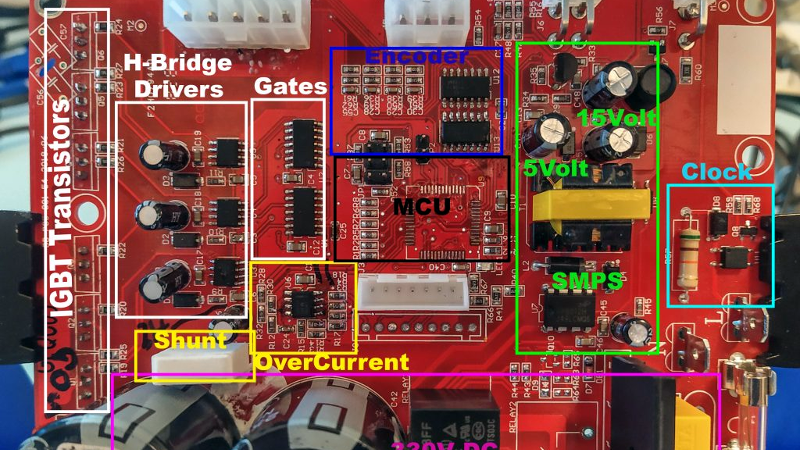
Now fully committed, [Haris] started mapping out the rest of the controller section by section. In the write-up on his blog, he visually masks off the various areas of the PCB so readers have an easier time following along and understanding how the schematics relate to the physical board. It’s a nice touch, and a trick worth keeping in mind during your own reverse engineering adventures.
In the end, [Haris] seems to have a good handle on what the majority of the components are up to on the board. Which is good, since getting it working again now means replacing the MCU and writing new firmware from scratch. Or perhaps he’ll just take the lessons learned from this controller and spin up his own custom hardware. In either event, we’ll be keeping an eye out for his next post on the subject.


For less than 10USD one can get an USB isolator from Ali*, why spare on that ?
This is why I have a variac and isolation transformer on my bench. I measure voltages with a cheap multimeter before I hook anything to my test equipment. Electronics can be dangerous. Old radios and TVs are rarely isolated.
For electronics newcomers would you car to explain how the variac helps here? Thanks
The variac is an isolated supply, i.e. it has a high voltage between its terminals but is not referenced to ground. So if or when a terminal is shorted to your device it doesn’t get any current running through it.
Ok thanks for your answer. So it’s basically a cheap isolation transformer? Less secure maybe than a full fledged/boxed one ?
s/secure/safe/
NOOOO! Variacs are inherently NOT isolated! Theirs might be, but NEVER assume a variac to be isolated!
No variac I’ve ever used has been isolated. I keep a couple of isolation transformers on hand for that job.
Exaxtly. VariAC is always supposed to be input referenced and therefore not isolated.
You ALWAYS need an isolation transformer before your variac in order to increase your safety. Nevertheless, you always want to keep your left hand in your back pocket when working on the device although it is behind an isolation transformer.
Variacs are NOT isolated. They’re a variable autotransformer. You need a variac and a transformer. I use a variac to gradually increase the line voltage while monitoring AC line current. This is done in case there are old failed electrolytic caps in the power supply. I have an old Heath AC supply that has a variac, isolation transformer and voltage/current metering for low powered items. This is important when working on any hot-chassis equipment like tube radios. Some older equipment has no polarized plug. The chassis can be hot or neutral depending on how you plug it in. The isolation transformer goes before or after the variac. Doesn’t really matter. But, EVERYTHING in the equipment under test may now be hot depending on where you have leakage to neutral or ground, if any. In an ideal world, if you connect an actual ground to any point in the circuit, everything else will now be referenced to that point. You probably won’t blow up your scope or computer but by connecting a ground but absolutely need to verify the potential of any point you intend to connect to test equipment. The basic idea is always test with a battery powered multimeter to line ground before connecting to test equipment or touching anything. This avoids most dangerous situations.
Yes, decades ago I mounted an isolation transformer onto a variable autotransformer (not Variac brand)
to get isolated AC.
If I’m lucky I can get 100 watts out of the thing.
A variac is a transformer with a rotary wiper (sliding contact), allowing dialing the output AC voltage from zero to (usually) a bit above line voltage. They’ve been around for decades.
The ones I have are **NOT** repeat **NOT** isolated.
I wonder why the clock section as such a big (1W it seems, maybe 2W) resistor?
If you RTFA he explains, that this circuitry extracts the line frequency from the AC input.
Most likely for zero crossing detection.
Thanks, I RTFA but the author merely guess and doesn’t explain, thus my question.
Its for the isolation between the two ends of the resistor. Its not for the power dissipation. If you use a 0805 or some really small resistor the mains voltage or surges could jump between the ends. It would be like the resistor did not exist. Not Good!
You need to look at mains voltage standards for isolation somewhere > 5mm. See the IPC pcb standards for correct clearance values.
The 50 Hz clock is probably used to time the closing of the relay after the bridge rectifier to prevent arcing (like zero cross detector) and may be used to time switching of the H-Bridge even though at high DC volts.
Not according to the schematic in the article. The relay bridges the inrush current limiting resistor and is powered simply from the 15VDC rail.
Happened twice where I worked, one time to me. First time it was practicant, he even had his own computer. Strangely/Fortunately only company owned monitor burned, his mac was intact but programmer literally exploded and among silence which ensued (breakers tripped), programmer cover made VERY loud noise when it fell back on desk.
Hope that the programmer mentioned was a device, not a person covered with something.
Yes, reading the article, it is clear from the beginning what is going to happen. But I have to admit that I might have fallen into this trap as well. non-isolated power supplies are getting rare these days. And there is a little transformer that looks very suitable for a small SMPS. I am afraid I wouldn’t have guessed this outcome as well.
This is a mistake one only makes once. Happened to me with 24V and a non insulated USB adapter, burned a hole right thought the PCB!
I made this mistake with a tube-type radio and a Heathkit VTVM (Vacuum Tube Voltmeter), maybe in 1975 when I was 13 years old. It’s something you never forget…
I needed a mains isolation transformer to work on a motor controller…
Ended up making with 2 transformers wired [primary : secondary] = [secondary : primary] from a dead APC UPS:
https://youtu.be/WMSdY_3KbEw
I applaud your use of salvaged UPS transformers in this fashion. Depending on the specific parts used, this could result in an isolator with a generous capacity, given the large core size of these types of devices.
While I’ve done the back-to-back transformer thing myself on several occasions, I hadn’t previously considered UPS transformers for this application… and this is why I read the comments on Hackaday. Great idea.
The Transformers where out of this APC UPS model SU2200R3X167
The UPS was rated at 2200 VA and they run the transformers in parallel.
So I would de-rate my setup to around 1000 VA.
IIRC, back to back Microwave Oven Transformers (MOTs) can also be used to build an isolation transformer.
(You might want to cut the HV windings off first.)
Unfortunately, UPS transformers are often made as autotransformers in order to save some copper.
An isolation transformer is a good solution, if you know to expect random devices to have an non-isolated power supply. But even more important is GFCI for *every* electronics bench. Preferably a 10mA model, which can often save even the microcontroller, in addition to your life.
As the novices at the school labs we were forced to wear “handcuffs” – a device strapped to both wrists, that tripped the work bench circuit breaker when it detected some potential difference between the wrist bands. It also liked to trip for no obvious reason fortunately, so every time it tripped, it was for no reason – or at least our lab teacher was so informed…
So it is obvious that PUFF the MAGIC DRAGON doesn’t just live by the SEA !!! I’ve had a few circuits go BANG myself and it is always a revelation. Other people nearby say what was that ? Then aside from my first response, not laughter, then lots of laughter. Circuits, fire crackers and gun shots.