If you’ve ever pushed the needle a bit on your Raspberry Pi, there’s a good chance you’ve been visited by the dreaded lightning bolt icon. When it pops up on the corner of the screen, it’s a warning that the input voltage is dipping into the danger zone. If you see this symbol often, the usual recommendation is to get a higher capacity power supply. But experienced Pi wranglers will know that the board can still be skittish.
Sick of seeing this icon during his MAME sessions, [Majenko] decided to attack the problem directly by taking a close look at the power supply circuitry of the Pi 4. While the official schematics for everyone’s favorite single-board computer are unfortunately incomplete, he was still able to identify a few components that struck him as a bit odd. While we wouldn’t necessarily recommend you rush out and make these same modifications to your own board, the early results are certainly promising.
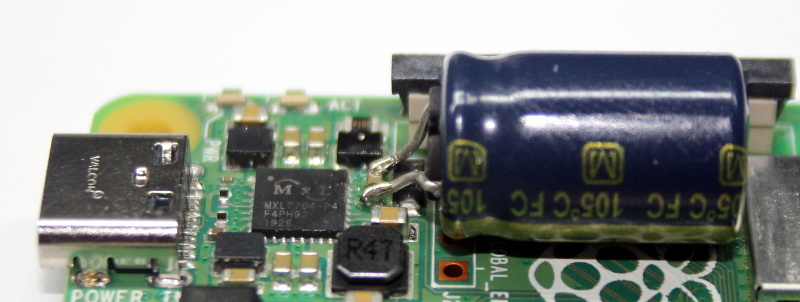
The first potential culprit [Majenko] found was a 10 ohm resistor on the 5 V line. He figured this part alone would have a greater impact on the system voltage than a dodgy USB cable would. The components aren’t labeled on the Pi’s PCB, but with a little poking of the multimeter he was able to track down the 0402 component and replace it with a tiny piece of wire. He powered up the Pi and ran a few games to test the fix, and while he definitely got fewer low-voltage warnings, there was still the occasional brownout.
Going back to the schematic, he noticed there was a 10 uF capacitor on the same line as the resistor. What if he bumped that up a bit? The USB specifications say that’s the maximum capacitive load for a downstream device, but he reasoned that’s really only a problem for people trying to power the Pi from their computer’s USB port.
Tacking a 470 uF electrolytic capacitor to the existing SMD part might look a little funny, but after the installation, [Majenko] reports there hasn’t been a single low-voltage warning. He wonders if the addition of the larger capacitor might make removing the resistor unnecessary, but since he doesn’t want to mess with a good thing, that determination will be left as an exercise for the reader.
It’s no secret that the Raspberry Pi 4 has been plagued with power issues since release, but a newer board revision released last year helped smooth things out a bit. While most people wouldn’t go this far just to address the occasional edge case, it’s good to know folks are out there experimenting with potential fixes and improvements.


What about the same problem with the other generations of boards ?
What about them? This post and hack is about the power issues on the Pi4.
I think what YDGES tried to ask was: “Would this, or something similar, apply to other generations of the Raspberry Pi boarsd?”
I’m surprised you were not able to understand that.
Very tactful ..🤭
you mean bridging the polyfuses and jumpering to the usb ports directly for full power devices
What do you mean, what about them? It’s a valid question to ask, no need to bite their head off!
For the concern about too much capacitance for a USB port, how about connecting the capacitor’s negative pin to ground through an IRL520, with it’s gate driven by a high value resistor to +5V with 2 diodes to it so when power goes down, the gate gets discharged to within 1 diode drop of ground for the next cycle?
cogo, this sounds interesting, got a schematic?
It’s not really a hack. It is a fix for an issue that plagued every single pi board. They continue to mess it up. Maybe they could learn something from it and the raspberry pi 15 will come without power supply issues, but i wouldn’t bet on it.
How the hell is this not a hack!? They’re soldering shit right to the board. What do you think a hack is exactly?
Not just a hack, but a bad one. All it does is cover up the fact that the power supply is inadequate. If it briefly drops below 4.65, this will hide that fact. Dropping below 4.65 is pushing stability. The real fix is, surprise surprise, get a decent power supply.
10 ohm resistor aside, it’s no surprise that the general fix for power supply issues also fixes this power supply issue :)
i kind of agree.
the old pi’s need this mod too.
Really? I have have owned a raspi 3b since it was launched and never had any issues using the 2.5 amp powersuply that I bought with it. But if I use a standard phone charger rated at max 2 amp at 5v then I have seen the power warning. Which is hardly surprising since they do not meet the specified power levels. Even when running with a 3.5 inch LCD screen attached. That’s with the armV7 cpu clocked at 700 MHz. Rasp-config have disabled the overclocking for my board. I have been using it to host my network controller which then runs in a docker container.
Works perfectly when using a no desktop Linux version. The small amount of Ram memory limits the desktop experience very hard and crawls to a halt if all physical Ram is allocated and its forced to swap mem. Like 2 chromium tabs. 😲🙂
What are you saying? You seem to say something about older Pi’s not needing this, but then you talk about something about memory limitatations and how you’ve solved it with running Linux without a desktop. Excuse my ignorance, but how do the two (or more) issues relate? Are you just rambling? Are you using RPi just because it’s cheap? Because it sounds like you’re on a “level” to use other SBCs more efficiently. Isn’t asking average RPi users to work without a desktop a little too much? (Specifically, me!) Can’t you recommend a board without this problem? Are you just bragging about using a Pi this way?
My 3 has way more issues than the 4 on the same power supply, which is kind of surprising.
I’ve used a “hack” for ages with troublesome Pis. A capacitor soldered to a female 2 pin connector which gets plugged into 5v and gnd on the GPIO. Momentary current spikes causing sag are an issue that plagues the more hungry Rpi’s.
A fix for these might be similar – esp. for 3B+, I think it uses the same PMIC as 4B? Also, I think previous boards have info in their schematics about how the undervoltage detection is implemented, IIRC it’s an analog circuit from passives switching a transistor that signals a GPIO processed by the VPU? Should be easy-ish to circumvent, just need to track it down.
Ah yes, like the “take the battery out of the smoke alarm” method of preventing house fires.
Yes, that’s exactly it!
You can disable the warnings by setting avoid_warnings=2 in config.txt, but that just hides the problem and can cause problems later on.
Until I’m in a position to actually fix this problem, I’d rather not see the warning, it’s obnoxious.
Do you also ignore the warning light on you car as well, right up to the point the engine blows up? Just get a decent power supply.
Yes jhughes, I don’t have a car but I totally would ignore the light if I could! Engine blowing up seems to be a nice side effect, it has never happened to me, again, no car, but now that you mentioned it, I’m thrilled even thinking about it!
Hmm, I should get a car ASAP. As soon as I do, I am sooo putting some triacetone triperoxide in my gas tank!
I still have a pi – 1 with a 1000uF capacitor soldered across the 5V. :-)
It’s actually from the first 10k units ever: It has the jtag connector installed.
Don’t break that thing! It will be a collector’s item some day.
I added a similar cap on a vga666 board over a 3B, that and adjusting the 5v line to 5,2V completely solved the undervoltage problems.
Tweaking the voltage up is a very practical solution, providing the subsequent voltage conversion is not via linear regulation. Does the board run hotter?
I don’t than the resistance is 10ohm because if the board draw 500mA than the voltage is 5V ie the Vcc will be 0V and will be reseted not low voltage warning (USB 5V – voltage drop 5V)
It is highly the meter accuracy problem. The photo seems to be over current resettable fuse which is protect if there are short circuit when there is wrong connection at pin connector to off board control.
Couldn’t you simply just put the same cap across the power lines on the usb jack, or make a short pigtail to put a cap inline on the power input completely removing the need to mod the board?
Have you seen the traces on the USB C connectors?! And I wanted to avoid anything dangling – this is all inside a nice die-cast case. You *may* get away with a pigtail, but it wouldn’t look good, and you want the capacitor as close to the point of consumption as possible.
There are pads on the back of the board connected to the USB power that are easy to solder to, fwiw. This is the route I’m looking at trying…
Yoooo I’ve been having the same issues with a Raspberry pi 3 B+ when trying to use USB sound cards. It wasn’t a faulty power supply/USB cable. Maybe I should give this a try.
If you have a powered USB hub, you might try that first.
Anybody actually tried that yet ?
I tried a powered USB hub with my pi 4 and a WD 1TB SSD. At first it seemed to solve the low voltage problem, but occasionally I’d still get a low voltage warning. I’d think a powered USB hub would solve that problem, and maybe mine is defective. I didn’t want to strap a powered hub to the back of the system I was building anyway, since the SSD would be the only thing plugged into it. I connected 5.0V from a buck converter (I had 12V to power the monitor handy) to the GPIO pins, and at first, it seemed to work, but still, every now and then I’d get a low-voltage alert. I increased the voltage to 5.15V (at the regulator, connected to the GPIO port with 24ga wire) and I haven’t had a low-voltage warning for about 2 weeks now.
Can’t you just bypass this by powering the pi from the 5v pins on the gpio?
I was having low voltage warnings on a pi 4 when using a ssd plugged into one of the USB 3 ports. Connecting the power to the 5V pins on the GPIO made it happen a lot less often, but it still happened on occasion. Raising the voltage to 5.15V seems to have solved the problem, but we’ll see what the long-term effects are. I suspect everything will be fine. In this case, I can adjust the voltage easily, this unit is running off a buck convertor with adjustable voltage and current limit.
The official Raspberry Pi power supply is 5.1V, 3A, so I can infer that this tiny overvoltage isn’t going to compromise the system.
Most USB poser supplies are over volted a bit to take into account the voltage drop at the end of the 3ish foot long cable.
That almost sounds like it was a desigend in feature to provide a way to sell a specalist power supply because it “fixes the problem”
Cos that NEVER happens….
I dont think he understand what he do…
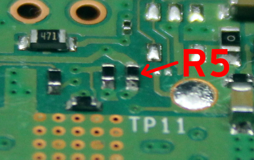
R5 and C12 is a filter for the supply for the power chip, not for the whole pi…
But while removing R5 and adding more C to the 5V line, makes the whole 5V line more stable.
imho better would be let R5 be 10R and adding more C to the Cs above (C3, C5, C7, C9)
btw he wrote about the USB spec, but dont see the pi breaks that already with the Cs above, they a direct connected to the 5V line
“I dont think he understand what he do…” I thought the same while reading the article. The best option ist to buffer the incoming 5-V-line.
I agree, I have forty years of experience in electronics and those components are there for a reason and stability will be affected fit some people. We don’t fit components to waste money!
the good old reverse engineering 😂😂
I would guess this was to limit the in-rush current, probably they should have used a ferrite bead followed by a larger capacitor and checked in simulation that the in-rush current didn’t exceed the USB spec (XmA+10uF). If it did then an RC circuit and a FET for soft start would just completely solve it and stay within spec.
You mean the resistor? No, it’s to (along with a second one) try and isolate electrical noise from the LDO power input which is used for the analog audio circuitry – a job it completely fails at. Yes, I’d have chosen a ferrite bead for that job, not a resistor.
why did they even do that? Any power supply designer worth his salt knows to use ferrites…
This^… I can appreciate your post.
Ferrite would only work if the glitches are tiny. It won’t fix a bad system level power supply design.
I don’t think that 10 ohm resistor is affecting anything relevant: it’s only on the pin for the PMIC’s own power supply, which is quite low power and noise sensitive: the resistor is probably just to help with filtering out some noise (it’s a mxl7704 if anyone wants to check the datasheet). It’s definitely not in the path of any of the current flowing towards the SoC. (There’s a similar arrangement for the input of the LDO which is used for the audio supply).
Yeah – if there really was 10 ohms in series with the supply, the typical 500mA draw would already drop the whole 5V!
And double up as a power-on light!
I see what you mean. It seems I mis-read the schematic. Maybe putting the BFC across one of the 22uF caps instead and leaving the 10R in there would be a slightly better arrangement.
RCX is correct, the MXL7704 datasheet recommends using an RC filter on the 5V_SYS lines.
“5VSYS pin should have a low pass filter in front. A 100nF capacitor between 5VSYS and AGND should be placed as close as possible to the IC” https://www.maxlinear.com/ds/mxl7704.pdf
What rev is your board? I only recently bought an RPI4 a couple months ago and have not had any power issues with it and I’ve hammered it pretty hard compiling kernels on the PI itself with all cores. I’m not running the desktop though so I wouldn’t get the power icon, does the error show up in the syslogs?
All the Pi OS I’ve used print an under voltage error to all consoles as well
The resistor is probably there to act as a fuse. This is used a lot in Eurorack synth modules. If something on the module goes bad, the 10R burns open, saving the rest of the system/power supply from the short.
I’m sure the BFC does some good; I’d also add a 10nF cap for additional high-frequency noise filtering.
no no fuse in this case, only a filter, nothing of the main current goes through this R, so no fuse…
The 10R forms a RC low pass filter for the undervoltage detection (below 4.6V) to filter glitches. The PMIC is supposed to use 8mA (idle) there. The datashee suggested 0.1uF, but they use 10uF cap. i.e. someone trying to mask the issue.
There are 2 issues that the RPi still choose to ignore.
– VUSB is not guaranteed to be 5V in the regular non-PD USB port nor would it supply higher than 100mA/500mA.
– The PMIC *need* a much larger bulk cap to handle any sudden increase in power
They really should switch to USB PD spec for a slightly higher voltage and use a properly sized bulk cap for the input. They are half way there already.
If the only thing that bothers you are the low voltage warnings (e.g. the Pi is not powering down), you can just disable them in the boot options, no need to grab the soldering iron here!
The warnings are there for a reason. You can hide them (which doesn’t solve anything, just hides them) or disable them, which then stops the turbo throttling, which can cause the Pi to crash. By fixing it you both remove the warnings and stop the turbo throttling from happening without causing any crashes.
Ah, a BFC470uF fixes the problem.
There’s not many things a BFC470uF can’t cure… Maybe they should try it on Covid-19…
Can’t find anything called a BFC470uF on google, but the article says to use a 470uF capacitor, and as you provided zero further details, I’m not sure how this adds to the article.
BFC = Big Effing Capacitor. I.e., if in doubt throw more capacitance at it.
Even then, just stack some compactors. There is no reason a X5R capacitor wouldn’t work. Grab the largest capacitance for the same size footprint and start stacking. Would look and be way more practical than a BFTHC (through hole).
Consider the DC bias effect and look at how many ceramic caps you’d need to pile up. For that 0603 footprint, I don’t think you can get more than 10 uF of effective capacitance out of X5R under 5 V bias. I think I’d rather install the single fat electrolytic.
lol, i always wondered what that flashing lighning bolt icon was on my Pi 3B. since i use an external 2.5″ hdd drive on it with Kodi software on the Pi, i assumed it was some kind of notification from Kodi. A signal for accessing the external drive or something like that. The Pi never shuts down though. So i think im fine.
It doesn’t shut down because when that lightning bolt appears it slows down to reduce power consumption. So you lose performance.
thank you, good to know.
everything will be a collector’s item one day…
the 10uF limit on USB is to protect the connector. With the huge capacitor inrush current when connecting the USB will eat the connector
No it’s not. It’s to prevent the PC from shutting down the power to the port from over current. The connector can take a whole lot more than that.
It is there to prevent a power brown out (e.g. hub) due to the inrush current needed to charge up the bulk caps. The brown out affects the VUSB power rail that might glitch the other devices and cause them to crash.
Wow, you can disable under outage warnings in one line in boot.txt jist FYI. Do it all the time. Done ot on the pi3, 4, and pi w works just fine.
Disabling is not fixing. If you hide them (=1) then the problem is still there: you still get throttling which is a PITA. If you disable them completely (=2) then you run the risk of under-power causing the Pi to crash.
I have modded every Pi 3 I have by adding 2200uF or more of capacitance to the 5V input. It really does make them a lot less “picky” about the power supply.
“While the official schematics for everyone’s favorite single-board computer are unfortunately incomplete”
While the official schematics for your favourite single-board computer are still not Open Hardware (OHW).
They can open source everything, BUT Broadcom won’t sell the chip so being OHW complaint is meaningless. Last time Broadcom shutdown Ordoid W, a RPi competitor, by not selling them the chips.
https://liliputing.com/2014/08/hardkernels-raspberry-pi-like-odroid-w-discontinued-month-launch.html
I’ve never encountered this and from the headline expected it to be about too-high voltage, so I learned something.
Time to buy my 3rd copy of The Art of Electronics…. and read it this time.
Geeez, these power problems are STILL going on!? I gave up on the RPi 3 or was it 3A or 3B or 3B+ or… Never mind. By the time I could actually buy the buggy thing it was already soon to be obsolete.
The Pi has never been a particularly well designed board even from the outset. Some initial bizarre design choices meant they were stuck with a bad design (I mean, who in their right mind would put a 3.3V and 5V power pin next to each other on a 3.3V board? That’s just asking for trouble…) When the Pi 1 came out, compared to the other boards that were around at the time, it was a real bag of ****. It just goes to prove that for any product to be successful it doesn’t need to be good. It doesn’t need to be the best. It just has to have tons and tons of cash behind it to hype it up.
All they’re doing now is pumping faster and faster SoCs and more memory at it without addressing the underlying design defects.
Oh, and who would choose a SoC that’s completely closed source so no one can actually use it? Only someone that works for that SoC manufacturer and gets a massive discount is who… Talk about eNepotism…
Edit: “Completely closed source” was the wrong phrase. I meant “NDA’d up to the hilt”.
You missed out the biggest reason the Pi took off and has proven so popular – its documentation and support has always been stellar, so far ahead of any rivals that its a joy to use… Pretty much any other SBC you are on your own, and might take weeks to get the damn thing to function at all. A Pi with the effort they put in to making it work and keeping the old ones supported just works, while often being cheaper, when the Pi first launched much cheaper than most alternatives..
As for why they chose Broadcom, that’s bloody obvious the core team worked there and knew what the chip could do and how to do it, so they could deliver a good product easily… Anybody with deep enough pockets to meet the minimum order, sign the NDA, etc etc can use any chip – heck Apple would probably let you use their new chip if you coughed up enough cash, its just how silicon markets are… And it is not like RiskV was ready to use when they started (or is now even – looks like its pretty close, but its only been in the last year or so from what I can see it became developed enough to really challenge for the job over an arm/amd64 at anything much…)
I bought a pi4 for a new retropie setup and have already toasted a sd card.
Pi3B+’s have worked out well for me. Even the pi zero has done okay.
Other then those two specific models one always ended up getting burned. I had a pi2 that had an appetite for wireless cards.
The Pi foundation needs to give up on this damnable idea that a pi is usb power able and go to a 9v barrel jack. It’s particularly disappointing that their USB C doesn’t negotiate using a higher voltage – what a waste of effort and a pointless conversion.
After spending days (probably weeks) of my life on debugging non functioning software, lost data, corrupted SD and USB drives, etc., I’ve given an oath to never touch a Raspberry Pi again until they fix their power problems.
And no … a custom 5.1V power supply is not the solution.
It took 5.15V to solve the problem for me, but that’s not practical for every situation, the pi in question is run off a buck converter with adjustable output voltage and current limit. I also connected the power via the GPIO, that made undervolt warnings less often on 5.0V.
I bet if you ziptied it to a 220,000uF 50V industrial coke can aluminum electrolytic capacitor on the backside and put a Pentium 4 heatsink on top, you could package the whole thing neatly in a standard 1 pound coffee can, with a few dozen ventilation holes and have no more voltage or heat problems.
;-)
I probably meant 2lb… or 900g… or whatever they are now… probably 850g if you’re reading this next month when they dropped it 50g and put the price up a buck.
Is coffee still sold in “cans”?
B^)
Absolutely. Chock-full-o-nuts still comes in an all metal tin can unlike most other cans you see now which just have a metal bottom stuck to a cardboard cylinder for a can.
Are you suggesting they should be made out of steel, like a proper “tin” can? Can is short for canister, which is any vaguely cylindrical container. I was buying large vac sealed bags for a while, but for some reason they went back to cans.
The cans will not degrade over time like the bags. Nor will the puncture easily.
I was having similar power issues when running a Pi3b/3b+ and the raspi 7in touchscreen. I found 2 things that were “fixes”. The first is if you are using USB then power it with 5.2v. The second was power the setup from the 5v GPIO header and put an electrolytic on there to stabilize the voltage.
The second one is the one I stuck with. I am using the setup to run “Smoopi” as a host for my Smoothieware based CNC devices.
What is curious about the image posted, if R5 is a 10 ohm resistor in series with the 5V0 supply, what does it power? I ask, because pushing however many milliamps through a 10 ohm resistor and a trace that thin can’t possible be the cause of the power supply issues, unless a serious design flaw was made.
It powers the PMIC which draws 8mA so there is an 80mV drop across it. Shorting this resistor removes this extra voltage drop.
Why stop at 470µf when you can have 44F?
I’ve been fighting with undervoltage warnings on my Octoprint box for a long time now. It doesn’t seem to matter how many amps the power supply is rated for or how thick the USB cable is. I’ve managed to get the undervoltage warnings down enough to call them rare but they still happen.
So my new toy to play with this weekend… A Juice4halt!
I just hope these scripts it depends on to shut down still work on the current poetterized Raspbian version which Octopi is based on. This support area doesn’t look like it’s been updated in a while and I see no mention of Systemd.
I think the Pi folks are finally learning about power circuits, a friend (who does switched power stuff professionally, so they are well-equipped to torture it) got some Pi Pico boards the other day, and they have one of the more robust power circuits I’ve seen on a general purpose dev board (See section 4.4 of the datasheet for schematic, it’s a RT6150 buck-boost with appropriate passives). Big step from the 1117 and prayer on most cheap dev boards.
If you power from VSYS to bypass the oring schottky you can get by down to 1.6V, and it’s absolutely in-spec from 2-5.6v (and maybe higher, played it safe with the sweep range), with maximum efficiency near 2.5-3V.
Admittedly, the Pico is only pulling something like 100mW so it’s a different class of problem, but it’s a big change from the variety of finicky supply behavior every generation of mainline Pi has had.
They probably just copy paste the reference/application circuit. They have made tons of mistakes over the years – quite ironic considering the open source people like to promote their “many pairs of eyes”.
It’s not like the Raspberry Pi hardware is open source in any way shape or form. On the parts that are “shared openly”, people quickly called out their errors, but that was of course after they were already running production.
As for the Pico, it does have a decent power system, but that’s a whole different beast from a Pi 4 of course.
Thou shalt not remove 10R resistors from a PCBA! A special kind of hell is reserved for those attempting this heinous act.
Reconciliation can only be obtained through the ritual removal (and subsequent burning) of all ferrite beads on power lines. Please note that I have nothing against L-C oscillators in general, nor do I discriminate based on relative permeability at higher frequencies.
It’s like those series motor resistors.. uh no it’s not. Those brave Pi engineers all 3.14 of them had a particular headache when the Pi starts up and that 10 ohm resistor is a band-aid. Spice it up! Compare some start-up with different wall warts (I bet they are all different even some of the same ones.) Compare some maming with pi-hole and other notables and then, oops, solve the real problem. Would do it myself but too many brain-cells have walked away. You guys and gals are the greatest! Thanks!
The power system of the Raspberry Pi definitely leaves a lot to be designed. (That was actually a typo but then I decided it fit the situation well so I left it. :))
The power system is obviously optimized for low cost, but I’ve always thought the lack of on-board buffer capacitance is kind of insane because it requires any current spike to be pulled through the USB cable. A USB cable of unknown origin, quality, wire gauge. It’s just asking for trouble, and only gets worse the more power each generation of Pi requires.
Adding the bulk cap is a good start to solve this, but I would recommend adding some MLCCs as well to deal with faster power spikes since electrolytics have high inductance and won’t be able to buffer those.
Of course, any problem is also an opportunity, so I designed the LiFePO4wered/Pi+ (https://hackaday.io/project/20909-lifepo4weredpi) to add proper power management to the Pi. :)
I always thought I was the only one finding the Pi power supply situation ridiculous. “It’s powered via USB, isn’t that nice, so you don’t have to buy a dedicated PSU*”
Isn’t his solution more complex than it needs to be? As far as I know the the 5v Pins are directly connected to the USB, so connecting a capacitor to the Pins would be way easier than soldering on the board. Should be standard on every shield out there, would solve a lot of problems.
*Your mileage may vary, use our USB PSU or best of luck.
The 5V pins are too far away from the power circuit. You want the capacitor as close as possible so it’s not affected by the impedance of the traces.
I agree, I would want that.
But when the alternative is no capacitor/a capacitor on the other side of the USB cable, and that works “partially”, then I would assume the cap on the header pins could make it work “sufficiently”
Power it via the power pins on the GPIO header and bypass all that shit completely. If you have a good clean power supply it works amazingly. I’m doing that with >600 systems to date. Yes. 600.
Alas that is not true. The 5V pins connect to the same 5V part of the circuit and go through the same regulator. It’s easier with the 5V pins to get a good high current power connection though, which helps. However that is not an option when the Pi is inside a die-cast case with no access to the pins.
The pi is an educational tool and works fine as such. Design your own or don’t buy it. I have them from the B forward and never experienced any of the issues discussed in the comments. Guess I’m just that lucky.
the lawmaker has logged on, complete with “educational tool” talking point, even. Look at summary of all articles where Pi is covered on Hackaday and tell me more about how it’s an “educational tool”.
I do design my own for commercial use, thank you very much. The Pi is being used to educate me in how to play old arcade games. As such, in an educational environment, it fails because of poor design. Educational != shoddy design!
Educational = shoddy design! Actually shoddy design = educational. Otherwise Intel or some corporate giant would have bought them out and probably scrapped it. RPi’s exist because giants did not see them as a threat. It turns out this hobbyist/edu market may be bigger than they thought, but I’m sure margins are tight. The proverbial example is how IBM considered DOS so non-threatening that they let MS license it to whoever they wanted. OS/2 was indeed superior, but DOS was good enough to start an OS monopoly empire. Not because DOS was good, but rather bad enough that IBM didn’t see M$ taking over. RPi is on a more humble level imo, but… remember how bad DOS memory management was?
Actually Intel did try their hand at the educational market. They lasted about four years before they gave up. They only managed to produce one board which was never really adopted by the community, despite giving away 50,000 of them.
So educational to you is half-assed crap that gets frustrating to run? I guess you either learn by fire or rage quit.
That’s a yes. I’m not going to rewrite my comment above, but if someone like Intel saw them as being useful outside the educational market, they would have been bought, picked over, and tossed out with the trash. Lately I’ve been reading about Corona and Eagle Computers, which beat out Compaq to market, and IBM crushed them with their lawyers. I might add that Pi’s are not only “educational”, but $35 half-assed crap. And Ti-84s were required by university courses at $100 a pop from mid 80s to 2010s without a single improvement. I’m hoping students now use scientific calc apps on their phones, but wouldn’t be surprised if TI still sold the same $100 calcs to schools.
Reported by mistake, sorry.
My fix was to get a 10amp adjustable 5.1 v power supply. No alerts ever since.
So now you have a little RPi board with a heatsink the size of a chimney sticking out of it, and that is glued to a Meanwell power supply brick hacked with a voltage adjust pot, a big black bakelite knob, and a two dollar LED DC voltmeter module from AliExpress that took six weeks to arrive. And oh yes, there’s a fan thrown in there somewhere, just in case. And all that is required to solve a badly designed power system that has remained broken across generations of RPi boards. Sigh…
It looks it is not a problem or not significant one. Otherwise people would choose better board.
Power issues on ALL raspberry pi boards is a design feature. It’s easy to blame the power supply for a board designed to be run intermittently off an SD card and tethered to a PC.
Power issues on all Pi boards are because people do not use adequate power supplies. Is really as simple as that. The official one, and many others, give no power supply issues (unless you plug in devices that need ridiculous amounts of power). So instead of spending money of a daft hack like this that won’t help prevent issues (it just masks the warning), just spend a few dollars on a decent PS. Do that and you can run any Pi 24/7 for years on end.
Why not solder the BFC into a TypeA USB plug and plug it into one of the USB sockets (who uses all four?)
Circuit diagrams for the various Pi’s are very incomplete, but I found an old one from 2012.
What it shows is the USB ports are powered directly from the +5V line, not via the USB controller
From this, there is no reason not to power the Pi from one of the TypeA connectors
https://www.raspberrypi.org/app/uploads/2012/04/Raspberry-Pi-Schematics-R1.0.pdf