When [Vitor Melon] found out there was a custom firmware (CFW) available for his Xiaomi Mijia M365 Pro electric scooter that would increase his top end speed, naturally he installed it. Who wouldn’t want a little more performance out their hardware? But while the new firmware got the scooter running even better than stock, he does have a cautionary tale for anyone who might decide to ride their Mijia a bit harder than the fine folks at Xiaomi may have intended.
Now to be clear, [Vitor] does not blame the CFW for the fact that he cooked the control board of his Mijia. At least, not technically. There was nothing necessarily wrong with the new code or the capabilities it unlocked, but when combined with his particular riding style, it simply pushed the system over the edge. The failure seems to have been triggered by his penchant for using the strongest possible regenerative breaking settings on the scooter combined with a considerably higher than expected velocity attained during a downhill run. Turns out that big 40 flashing on the display wasn’t his speed, but an error code indicating an overheat condition. Oops.
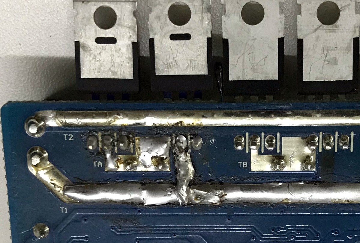
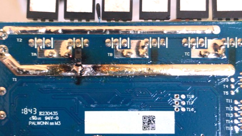
After a long and embarrassing walk home with his scooter, complete with a passerby laughing at him, [Vitor] opened the case and quickly identified the problem. Not only had the some of the MOSFETs failed, but a trace on the PCB had been badly burned through. Judging by the discoloration elsewhere on the board, it looks like a few of its friends were about to join in the self-immolation protest as well.
After a brief consultation with his graybeard father, [Vitor] replaced the dead transistors with higher rated versions and then turned his attention to the damaged traces. A bit of wire and a generous helping of solder got the main rail back in one piece, and he touched up the areas where the PCB had blackened for good measure.
A quick test confirmed the relatively simple repairs got the scooter up and running, but how was he going to prevent it from happening again? Reinstalling the original firmware with its more conservative governor was clearly no longer an option after he’d tasted such dizzying speeds, so instead he needed to find out some way to keep the controller cooler. The answer ended up being to attach the MOSFETs to the controller’s aluminum enclosure using thermal pads. This allows them to dissipate far more heat, and should keep a similar failure from happening again. You might be wondering why the MOSFETs weren’t already mounted this way, but unfortunately only Xiaomi can explain that one.
With their rapidly rising popularity hackers have been coming up with more and more elaborate modifications for electric scooters, and thanks to their wide availability on the second hand market, it’s likely the best is still yet to come when it comes to these affordable vehicles.


You are much better off using AWG #10 solid wire for patching the *high current* traces on the PCB. Solder is a piss poor conductor compared to copper. So if the copper trace burnt out, what would you think that would do to solder?
https://forum.allaboutcircuits.com/threads/conductivity-of-solder.41295/
>A general “rule of thumb” is that solder has roughly 5x the resistance of copper.
Well lets think about this so solder is about 5x the resistance of copper but I suspect cross-sectional area of the conductor has been increased 3x (incredibly conservatively).
So I guess copper would be a better conductor.
Lets think of the other end though, whats the consequence?
Well Power = I*V, assuming a voltage circuit (rather than say constant current).
P = IV, V = IR, P = V^2 / R
So power is inversely proportional to resistance in a voltage controlled circuit.
This means that the solder connection dissipates LESS power so is cooler.
Not only this but the bulky solder connection has MORE surface area to dissipate that heat (it’s less conductive which means more solder is needed for any amount of power) so using a some copper wire like you suggest is not a great idea.
If this analyses surprises you, touch some wire wool to a 9v and watch it burn up. Now touch an insulator. Nothing.
Looks like you’ve confused a few things there…
>>This means that the solder connection dissipates LESS power so is cooler.
You’ve chosen P = V^2/R to point out that with a higher R, there would be less P (when solder is used).
But let’s choose P = I^2 * R
Ooops, now with an increase in R, the P increases… and that would be the proper way to look at it.
The “some copper wire” like you described it sounds quite different than “10awg copper wire”, proposed to the guy you’re responding to, which is typically rated for 50A of current.
So this analysis did surprise me. Your example even more. You’re suggesting that by testing with an insulator, there is now dissipation. Well done. But if you take your example back to the scooter – the author had already experienced that when the circuit was isolated (broken traces etc), it wouldn’t run. And that’s ultimately the goal of the circuit.
Gosh how can you be so wrong and so high and mighty.
The scooter has a battery which outputs a maximum open circuit voltage. The higher resistance between the poles the less current and the less power is used (and dissipated.)
How do you justify holding current fixed in your analysis? As opposed to a fixed voltage which is what a battery provides?
well no the situation was that when braking and regenerating, the scooter would blow up.
So the situation is that the motor is spun by gravity, which then a generator.
That power generated in that motor _really_ wants to go somewhere. So it’s going to start pushing that current really hard. Whatever resistance is in between the plus and minus poles (the circuit that blew up) is basically a given, not the voltage, as you imply. The voltage will just increase to whatever is dictated by I^2*R
It’s all very well that a battery has a maximum OCV, but during regenerative braking the motor will keep pushing that current and if that power can’t go anywhere, it will generate voltages higher than the battery.
Especially if the battery can’t take the high amounts of power suddenly provided during regenerative braking.
when I said “motor spun by gravity” I of course mean that the person on the scooter is going down hill, and besides energy stored in momentum, gravity will also want to keep that scooter moving and is providing more energy.
If the trace was across the battery (as in connected between the two battery terminals) then going by voltage would be correct.
But in this instance, the trace is in line between the battery and motor – the trace doesn’t have battery voltage across it, it has almost the same voltage at both ends, and the big voltage change is over the motor, which is what’s really setting the current.
The only voltage that this trace sees is from it’s own resistance as current is forced through it (by the motor), V(trace)=I*R, giving P=I^2*R (which is also the same as V(trace)^2/R)
(V(trace) isn’t the same as V(battery), and in this case with the motor charging the battery V(trace)=V(motor)-V(battery), minus any other voltage losses (like in the MOSFETS), and is probably much smaller than the motor/battery voltages)
Hope this makes sense!
Wow, such a fundamental thing.
The power dissipated the PCB trace (that blows it like a fuse) is I^2*R, Voltage does not need to be considered until the combined trace and motor series resistance is getting closer to the internal resistance of the battery and is forming a divider.
Copper is both a better electrical conductor and a better thermal conductor. It allows more current to flow than than the PCB trace could, do duet to its cross-sectional area.
Solder is very problematic in high current or high temperature applications.
I would use a copper wire as well though I bet his solder-bodge works fine. I’d be willing to bet the area of a cross section of that solder augmented trace is way more than 5X the original copper trace. A 2 Oz trace is going to be less than 3 mils. The solder blob is likely to 50 mils. But, he would be well served to run it hard on the bench and measure the temp rise of the traces.
Don’t forget that the traces are already at a weaken state, so they might not stand another melt down. With the large diameter copper wire, it means that they are now running at a much lower temperature and would no longer burn out. It is one of those things that it cost a little bit of time and material, but save you time in the long run not having to go back and repair the same thing over and over again.
>I’d be willing to bet the area of a cross section of that solder augmented trace is way more than 5X the original copper trace.
If the original traces already have solder over it, then overall it doesn’t improve over the original. I think that’s not I would bet for. Looking at the trace above it, it is clean and already has solder. (otherwise, you would see someone scraping out the resists and cover the traces with solder.) So chances are that that’s what the broken trace originally has. Actually it has gone worse – part of the traces are only connected by solder.
BTW solder have much lower melting point than copper, so if they fail they might splatter molten solder to other parts of the circuit in a high vibration environment. :P
Lot of ifs in that that. Who knows that the original state was. But like I said, I would have used copper to augment rather than solder. Would like to see the results of bench testing for temperature.
When the solder is melting, the system has already failed catastrophically.
Hey, thank for you commend, i actually used a copper wire, but is covered by the solder.
The main power rails for the MOSFETs are completely drowned in solder from the factory.
I’ve actually seen people add copper wire to those rails, submerging them in the already present thick solder traces and adding more solder in the process. It did help with the high current but it poses another risk of actually burning the battery connector and/or battery cables.
I fried a controller once, but the only physical indication was the slightly melted battery connector and one of the cables burning and snapping off from that connector. And I didn’t beef up the power rails or anything.
It is magic white smoke that leaves a shit stain on the board.
It seems like the manufacturer made an engineering decision (remember, engineering is about tradeoffs) regarding thermals and maximum regenerative braking, which the “CFW” ignored. I don’t see any way this wouldn’t be the fault of the CFW, since it’s clearly operating outside of conditions that the device was designed for.
(FWIW I’m all for doing anything you want to devices you own, but don’t be surprised, or mad at the manufacturer, when things don’t go your way)
The operator is ultimately responsible for the way the toll their usage takes on the vehicle.
If I ruined my cars clutch you wouldn’t blame the ECU you’d blame my abusive driving.
I try to adhere to this general principle for any mode of transportation.. “If you’re gonna fly/ride/drive it like a jet fighter, maintain it like a jet fighter.”
The CFW-Generators I know have recommendations for safe values – but you can override them. So you get what you asked for…
Usally the motor gets roasted first (it has no temperature sensors built in). This is the first time I see a burned controller board from someone who did not increase the battery voltage.
The primary issue was setting the e-braking strength to maximum, which is strongly advised against for precisely this reason.
The system is designed to dump the energy produced from the braking back into the battery rather than dissipating it as heat, for efficiency’s sake. Which works fine most of the time, but when the battery is already full that energy goes to heat *anyway*, but instead of in a braking resistor with a lot of cooling capacity it’s in the mosfets. With the braking strength at the lower levels this happens slowly enough that the risk is minimal, but not so when on maximum.
Xiaomi responded with a BMS firmware update that reduced the maximum charge level of the battery pack to provide a bit more headroom for people who insist on this configuration, but it’s still not perfect.
The original MOSFETs were Rds(on) 4.1 miliohms, he replaeced them with MOSFETs of Rds(on) 7.8 miliohms.
I think that will come back to bite him.
You are probably write, but this was just a quick fix, I intend to change to the originals when it arrived from china (3 months later) but i got lazy and forgot about it.
I’ve been riding for more than a year and rode 1.000km+ since then. So i think it was a quick definitive fix, for now
Always clean off the carbonized (black) parts of the PCB, they act as high value resistors. In bad cases I have had to cut out pieces of PCB and replace them with epoxy.
It look likely given the highly localised damage to the track that the trace failed quickly in response to the failing MOSFET. Mosfets usually fail short circuit ( at lest initially :-) ) so i expect the repair will be fine . the regen issue at high speed was probably more about over voltage than over current. damaging the mosfet then the subsequent short circuit quickly blowing the track. i expect his repair will be fine as long as the chosen mosfets are kept within thier safe operating area.
The same reproducibly happens on the original firmware after a long ride up a very steep hill.
Everything carying high current in the “Pro” version is brutally underdimensioned.
After my first and only RMA for that problem I decided to replace the kapton tape they used instead of thermal pads and do some other modifications like strenghtening the PCB paths to no avail. Problem reoccured and this time the molten solderblob shorcircuited battery’s uart and +50Vbus and also destroyed not just the mosfets but also one of their drivers.
Also motor connectors were slightly melted because they were not gold plated and were badly crimped and not rated for the current, etc… Chinese piece of shit.
It’s not intended for “long ride up very steep hills”. If you buy a cheap car and insist on driving it as if it’s a high-performance sportscar, is it really the manufacturer’s fault when the engine blows up?
I would expect a high wear of parts but not for an engine to blow up in a waranty period (2 years min here in EU). The whole thing whether it’s an ICE or an EV drive train is packed full sensors and computer disallows working outside of designed limits even on very cheap cars.
Also very steep hills are how many cities looks like in Czech republic, Slovakia, southern Germany, etc..
If I hadn’t made modifications for better cooling I could have RMAed it for 2nd and 3rd time and then I would have had a right to get my money back (by EU laws).
Hell, even my RC flying things have wires and traces much beefier per same amount of current than the M365 Pro scooter.
Two things.
1. One way to build up traces that handle higher current is to use solder wick for the bridges, and solder the wick in place. That way you get a big thick conductive bridge that is made of copper AND solder in a strong composite.
2. Sorry for the nitpick, but it’s “braking,” not “breaking.” Unless it was a really clever pun because the controller really did break. In case of the latter, carry on :-)