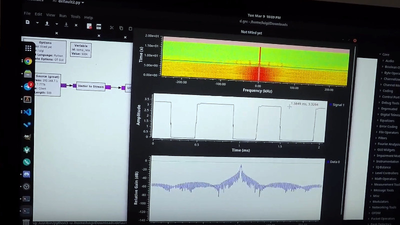
With the profusion of cheap RTL-SDR devices and the ever-reducing prices of more capable SDRs there might seem to be little place left for the low-bandwidth devices we’d have been happy with a decade or more ago, but there’s still plenty to be learned from something so simple. It’s something [Luigi Cruz] shows us with a simple SDR using the analogue-to-digital capabilities of the Raspberry Pi Pico, and since it works with GNU Radio we think it’s rather a neat project. CNX Software have the full story, and and quickly reveal that with its 500k samples per second bandwidth it’s not a machine that will set the SDR world on fire even when pushing Nyquist’s Law to the limit.
So with the exception of time signals and a few Long Wave broadcast stations if you live somewhere that still has them, you’ll need a fliter and receive converter to pull in anything of much use radio-wise with this SDR. But a baseband SDR with a couple of hundred kHz useful bandwidth and easy hackability through GNU Radio for the trifling cost of a Raspberry Pi Pico has to be worth a second look. You can see it in action in the video below the break, and if you’re at a loss for what to do with it take a look at Michael Ossmann and Kate Temkin’s 2019 Superconference talk.


“will set the SDR world on fine” -> “Fire”?
don´t play with fine!
I’m the finestarter, twisted finestarter
This is fine.
http://gunshowcomic.com/648
(Fixed. Thanks.)
Phew! could have been fined for that mistake…
After the dumpster fine of 2020…
My fliter caught on fine!
500ks/sec is definitely good enough for checking if your new gizmo is doing anything at all. Most of the times, that’s whats exactly needed
This.
I used my RTL-SDR a bunch of times listening in on ATC when I got it 10 odd years ago. These days? I fire it up to check for presence of RF during late night confused debugging sessions. It’s a waste, sure, but buying a SA would be even more so (for this specific purpose)!
Picking up time signals seems like a valuable thing to do. I have made a couple of clocks using an external time signal receiver + Arduino and the black-box nature of them is annoying. And they are not all that cheap.
What’s a good way to practically pick up those signals (like the German 77KHz and UK 60KHz) in a city?
No amount of blood sweat and ferrite rod antenna seems to work for me?
I briefly had some success with a board I picked up on Amazon (from a Canadian company of all places). But it’s output has long since become nonsense.
I live near a shipping yard and assume there must be terrible interference.
I used the PV Electronics one, though it seems to be out of stock now (and the Canadian source has dried up)
I think that a part of the difficulty is that the important part of the signal comes at the end. You get a synch signal, and then a minute later get the time data that you want. I had more luck with Arduinos that had a crystal oscillator and a more stable internal time base.
I think that what would be needed would be some sort of statistical processing, where the data packets would be assumed to the static apart from the seconds, and the incoming data would be synched to the existing data to recover the clock in case of drift.
However, you only need to get a good timestamp every couple of hours, so I have put up with the flakiness.
I have the library that I used on GitHub, but embarrassingly I can’t recall where I got it from, and I don’t see any attribution in the code. https://github.com/andypugh/LEDClock/tree/master/radioclock
This is fantastic thanks.
Indeed I’d be happy with one full minutes data once a week!
The best source of 60 or 77kHz receivers is… radio-controlled clocks. Under £10 on Amazon or eBay. They contain a separate receiver board, connected via open-collector wired-or logic, so you can just solder 3 wires on (ground, enable, signal), anhd you still have a working clock, no need to destroy the clock to get the received signal! The receiver takes around 10 seconds to lock when you ground the ‘enable’ input, but don’t keep it permanently grounded or it will drain the clock battery.
To synchronise to MSF, ignore the long sync pulse at the beginning of the minute and just use the framing code at the end (the last 8 bits are always 01111110, and this pattern can’t happen anywhere else.)
To sync DCF77, there is no carrier drop at second 59 so a drop 2 seconds after the previous one is the start of the minute.
Thanks for the insights, I had been watching diligently for the 500ms CW off minute marker but you make a good point about the framing code. The NPL technical document only mentions it in passing.
Back in the day, saw one of the old Maplin kit ones work fine in the middle of Manchester. Ground floor of a building, that was almost a basement with the earth banked around it.
Aha, here’s where they published it in the magazine… https://worldradiohistory.com/UK/Mapelin/Maplin-Electronics-1991-11.pdf
Very nice, Maplin is sorely missed I live(d) within 5 minutes walking distance to a medium sized Maplin.
Didn’t know they had a magazine let alone one with PCB designs ready to etch. Explains why there was always a sizable dusty and untouched bottle of Ferric Chloride in every shop.
Figure 10 is better than the NPL’s websites “technical document” describing the MSF slow code.
I’m doing a lot more error checking their code snippet.
That magazine is very nice indeed.
Thanks for the link to the Maplin magazine! Now I need to go and find the rest of them!
The content is a bit like Silicon Chip magazine here in .au except that Silicon Chip never had a real shops. Maybe that’s why the magazine has somehow survived: http://www.siliconchip.com.au
Disclaimer: I subscribe to Silicon Chip. It’s not cheap but I have never had a year (since 1990) that I’ve regretted paying!
First direct sampling SDR with a micro I know of is https://www.i2phd.org/armradio/index.html
Six years ago it was already sampling at 1.8 MHz and at the same time doing CIC, FFT, FIR, NCO and decoding.
https://www.youtube.com/watch?v=BtLrOLKpgtM&ab_channel=AlbertoGarlassi
Now I’m playing with a 5$ STM32H750 with a sample rate of 10 MHz. With undersampling it’s good for 20 meters and probably beyond.
Still work in progress, https://github.com/alberto-grl/750RTX/tree/USB2.
When it comes to higher sample rates, Xilinx have been plugging an FPGA with a built in ADC capable of about 4Gsps. Suspect that would cost a fortune, and run rather hot.
With fairly cheap hardware (eg. Teensy) capable of 600MHz, I’d certainly like to see a faster ADC. A modest 120Msps (5 clocks per sample) should cover up to FM, and over/under sampling should cover up to the 2 metre band.
Maybe even strip the ADC out of the microcontroller, and use the space to implement DSP functions?
There is no “modest” 120 Msps ADC. Then you have to get the data in the MCU. No common interface can do that, it is the realm of FPGA. Then you have 5 clocks per sample to decimate the signal. Good luck with that. For now STM ADC is the only one that can achieve this performance, AFAIK.
Don’t some NXP MCU’s have 20Msps and even 80Msps ADC’s?
I recall the Airspy SDR receivers using those.
Airspy receivers use a standalone RF chip, then process the downconverted baseband signal in the MCU. This is what is needed for good performance. Even if an internal very fast ADC would exist then, without specialized hardware, a generic MCU can’t possibly process such a big flow of data. Also, internal ADC are limited in performance by the noise from the rest of the MCU.
Anyway you are right. This Pi Pico ADC (I don’t understand why it is called SRD. The SDR part is taken care by GNURADIO) is limited in bandwidth by a factor of 10 because the author was looking for a way to use the new MCU that nobody needs.
Where are you in the world that there are FM broadcasts under 60 MHz ? (some of the former Soviet republics did use 65.8–74 MHz, but I do not know of any under 60MHz)
(hint: nyquist frequency sampling at 120MSPS is 60MHz)
Or do you have an external 87.5 MHz to 108 MHz bandpass anti-alias filter and are undersampling the frequency reversed alias.
Trying to be generous I would say that they were assuming I/Q sampling?
That would mean two 120Msps ADC’s which could not possibly be handled by a 600MHz Teensy CPU.
Pity it doesn’t manage 1Msps… sampling 455kHz IF of a traditional superhet receiver would be a _very_ viable option.
Still, there’s nothing stopping you from down-converting 455kHz to 255kHz (200kHz IF); thus making it a triple-conversion superhet frontend. Put a I²C-controlled LO in control of that front-end, and you’ve got a fairly agile hybrid superhet-SDR.
This reminds me of tricks done a decade or so back where a pc soundcard was used as the detector, and at the very limited “IF” frequency it could achieve. A separate superhet circuit was then used to convert the higher frequency to that the sound card could handle.
The addition of a Tayloe mixer and a local oscillator and using two adc inputs for I and Q could make a capable receiver.