The Onion Tau LiDAR Camera is a small, time-of-flight (ToF) based depth-sensing camera that looks and works a little like a USB webcam, but with a really big difference: frames from the Tau include 160 x 60 “pixels” of depth information as well as greyscale. This data is easily accessed via a Python API, and example scripts make it easy to get up and running quickly. The goal is to be an affordable and easy to use option for projects that could benefit from depth sensing.
When the Tau was announced on Crowd Supply, I immediately placed a pre-order for about $180. Since then, the folks at Onion were kind enough to send me a pre-production unit, and I’ve been playing around with the device to get an idea of how it acts, and to build an idea of what kind of projects it would be a good fit for. Here is what I’ve learned so far.
What Does It Do?
The easiest way to visualize what the camera does is by using the example applications, starting with Tau Studio. It is a web app that runs locally and can be viewed in any browser, and shows a live depth map and 3D point cloud generated by the attached camera.
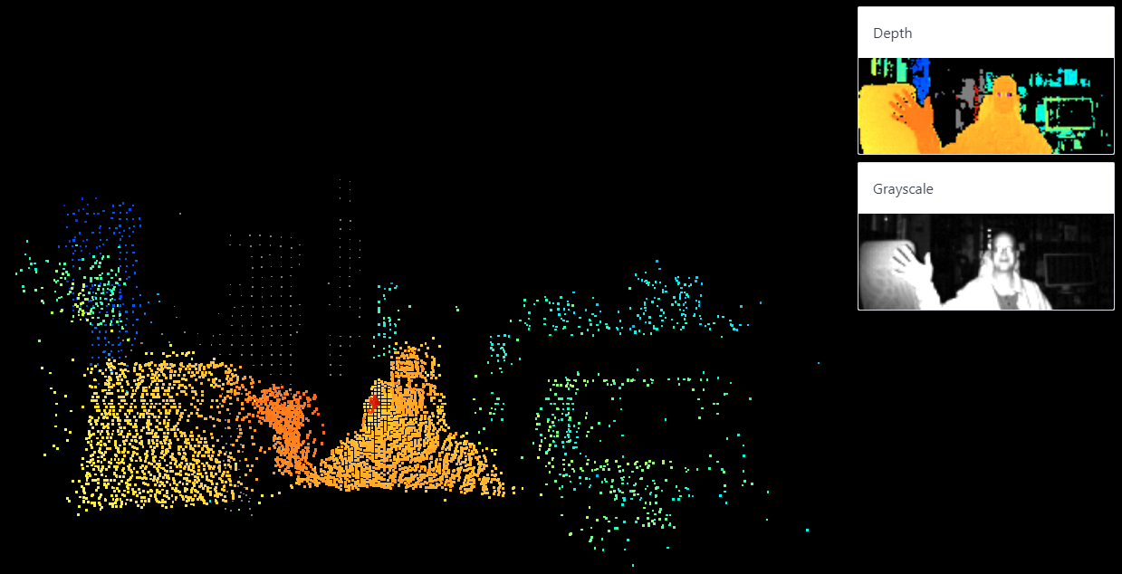
Tau Studio (and particularly the point cloud generation) works best in room-scale applications. The point cloud gets weird if things get too close to the camera, but more on that in a bit.
What’s It For?
The 3D depth data generated by the Tau camera lets a project make decisions that are based on distance measurements in real-world spaces. The way that works is each depth frame from the camera can be thought of as an array of 160 x 60 depth measurements representing the camera’s view, but it can provide additional data as well.
A bit of Python is all it takes to request things like depth info, a color depth map, or a greyscale image. Frames are also almost trivial to convert into OpenCV Mat objects, meaning that they can be easily passed to OpenCV operations like blob detection, edge detection, and so forth. The hardware and API even support the ability to plug in and use more than one camera at the same time, configured so they do not interfere with one another.
Device and Setup
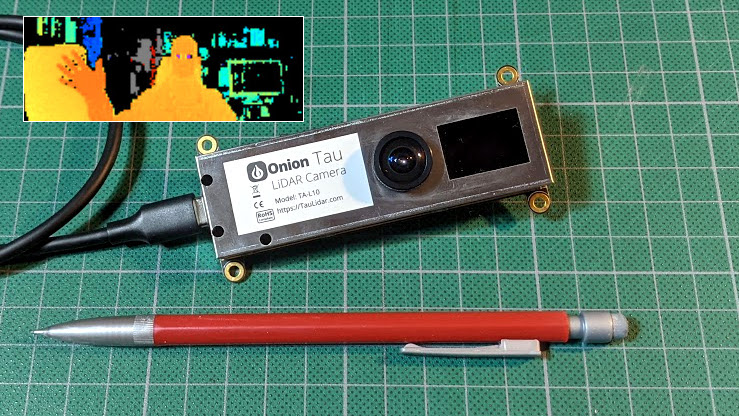
The Onion Tau is fairly small, with four M3-sized mounting holes and flat sides that make it easy to mount or enclose, and a single USB-C connector. It has a single lens, and next to the lens is a dark rectangular window through which IR emitters blink while the camera is in operation. Be sure to leave that area uncovered, or it won’t work properly.
Both power and data are handled via the USB-C connector, and a short cable is included with the camera. I found that a longer cable was extremely useful during the early stages of playing with the hardware. I used a high quality 5 meter long USB 3.0 active extender cable, which seemed to work fine. During early use, I was moving the camera around in all sorts of ways while running example code on my desktop machine and watching the results. It was a lifesaver because it allowed me to freely move the camera around while experimenting.
There’s a good getting started guide that walks through everything needed to get up and running, but to get a good working knowledge of what the camera is (and isn’t) good at, it’s worth going a bit further than what that guide spells out.
Testing and Building Familiarity
If I had one piece of advice for people playing around with the Tau to see what it does and doesn’t do well, it would be this: do not stop after using Tau Studio. Tau Studio is a nice interactive demo, but it does not give the fullest idea of what the camera can do.
Here is an example of what I mean: the point cloud in the image below turns into a red, hourglass-shaped mess if something is too close to the camera. But that doesn’t mean the camera’s data is garbage. If one watches the Depth window (top right from the point cloud), it’s clear the camera is picking up data far better than the distorted point cloud would imply.
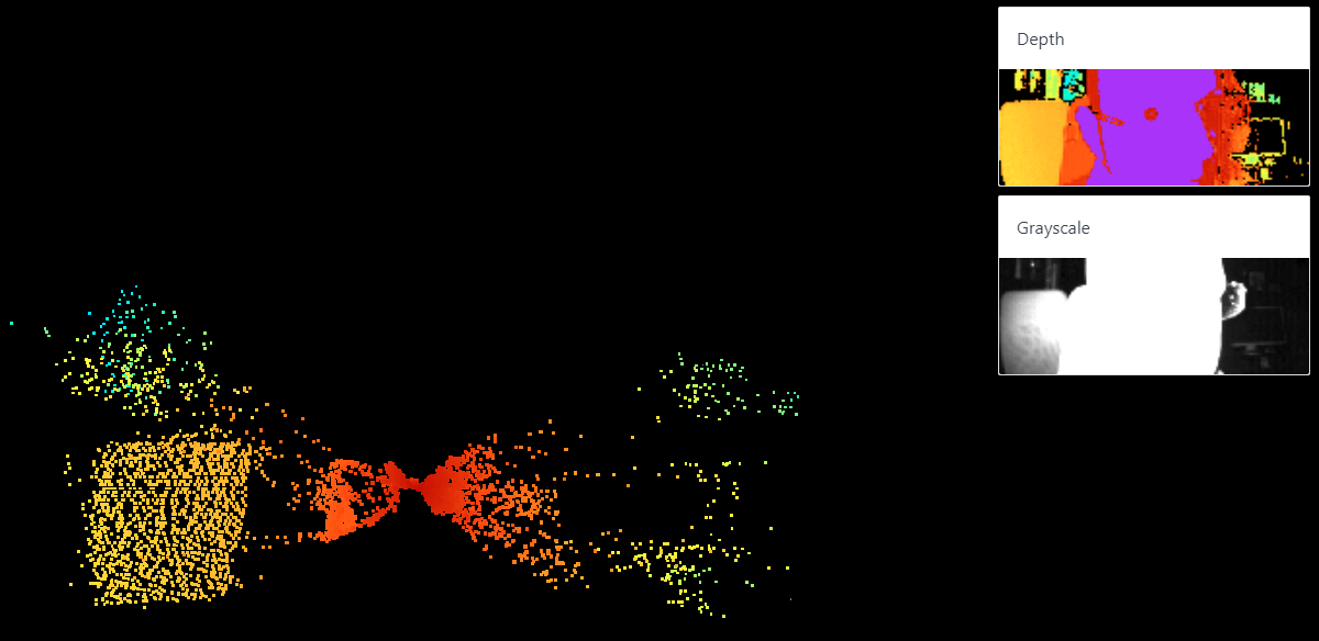
This is why it is important to not limit oneself to looking at the point cloud to decide what it is that the camera can and cannot do. The 3D point cloud is neat for sure, but the Depth view gives a better idea of what the camera can actually sense.
To get the fullest idea of the camera’s abilities, be sure to run the other examples and play with the configuration settings within. I found the distance.py and distancePlusAmplitude.py examples particularly helpful, and playing around with changing the values for setIntegrationTime3d (a bit like an exposure setting), setMinimalAmplitude (higher values filter out things reflecting less light), and setRange (adjusts the color range in the depth map) were the most instructive. The GitHub repository has the example code, and documentation for the API is available here.
In general, the higher the integration time, the better the camera senses depth and deals with less-cooperative objects. But if objects are getting saturated with IR (represented by purple in the depth map), reducing integration time might be a good idea. The amplitude view is a visual representation of how much reflected light is being picked up by the sensor, and is a handy way to quickly evaluate a scene. A higher minimal amplitude setting tends to filter out smaller and more distant objects.
What The Tau is Best At
The Tau seems to work best at what I’ll call “arm’s length and room-scale” operations, by which I mean the sweet spot is room-sized areas and ranges, with nothing getting too close to the camera itself. For this kind of operation, the default settings for the camera work very well.
The camera does not deal with very small objects at close ranges without tweaks to the settings, and even then, chasing results can feel a bit like fitting a square peg into a round hole. For example, I was not able to get the Tau to reliably detect things like board game pieces on a tabletop, but it did do a great job of sensing the layout of my workshop.
Mounting the Tau onto the ceiling and looking down into the room, for example, gave glorious results and could easily and reliably detect people, objects, and activity within the room.
Reflective objects (metal tins and glossy printed cardboard in my testing) could be a bit unpredictable, but only at close ranges. In general, the depth sensing was not easily confused as long as things weren’t too close to the camera. For optimal results, it’s best to keep the camera at arm’s length (or further) from whatever it’s looking at.
An Affordable Depth Camera, With Python API
The Tau is small, easily mountable, and can be thought of as a greyscale camera that also provides frames composed of 160 x 60 depth measurements. A bit of Python code is all it takes to get simple frame data from the camera, and those frames are almost trivial to convert into OpenCV Mat objects for use in vision processing functions. It works best at arms-length and room-scale applications, but it’s possible to tweak settings enough to get decent results in some edge cases.
The Python example applications are simple and effective, and I want to reiterate the importance of playing with each of them to get a fuller idea of what the camera does and does not do. Tau Studio, with its colorful 3D-rendered point cloud, is a nice tool but is in some ways very narrow in what it does. Watching the point cloud doesn’t paint the most complete picture of what the camera does, and how it can be configured, so be sure to try all the examples when evaluating.


So it appears to be a lower speed, lower resolution version of, a leap motion, all be it slightly more open source, with a much longer range and possibly a bit cheaper. Could be interesting for robotic vision as well as interfacing, possibly even creating quick 3D models. If mirrors and lenses were added perhaps the resolution and focal length could be increased at the expense of coverage. It could be interesting to combine two or more of these.
Is this ToF meaning something akin to ST’s FlightSense technology but instead of a single point, it has actual resolution?
“This is a ground-breaking technology allowing absolute distance to be measured independent of target reflectance. Instead of estimating the distance by measuring the amount of light reflected back from the object (which is significantly influenced by color and surface), the VL6180 precisely measures the time the light takes to travel to the nearest object and reflect back to the sensor (Time-of-Flight).”
How is it lower speed though? The entire point of ToF is to literally send a photon (or many) and then as quickly as light travels, read the data back.
Go ahead and again wait until this is manually read so it can be posted a day later and after everyone else has posted. and a dozen other articles are posted ahead of it. Akismet is annoying.
This is indirect ToF (Kinect 2), not direct ToF (iPhone). In indirect ToF, the outgoing light is modulated with a RF signal (in the 10s-100s of MHz) and the signal is recovered at each pixel and the phase demodulated. Direct ToF uses quick laser bursts and single-photon detectors. Indirect ToF is cheaper, but has limited range due to phase ambiguity.
I’ve been wondering about this for a while, awesome succinct description
I was wondering about that as well. I thought there was no way the LEDs would be shining light that is in phase. I’m pretty astounded that the image sensor can detect a modulation in the MHz range as well.
The phase Sam talks about is the phase of the modulation frequency. It’s not the phase of the light itself.
In the imager each pixel consists of two subpixels. Only one of the two is active at any given time. The imager is able to switch between these two subpixels with the modulation frequency. At the end of the exposure time those two subpixels can be read slowly.
It seems, that characters like parenthesis and quote marks trigger the Spambot Sensor really easy, especially if more than one of them are side by side. Also Hyperlinks
Could this be a very quick bed-leveling sensor for 3d printers? Why even probe if you can take a snapshot?
No way is it accurate enough for anything other than a really coarse level. ToF LIDAR is not really a good solution for sub-millimeter accuracy, which you need for bed leveling.
I imagine there are better ways of bed-leveling than spending $180.
I’ll level your bed for only $100
My idea is to have a pair of vertical rails on the carriage, on which the print head is mounted in a way that the print head can slide up and down by a couple of millimeters. Add a microswitch to detect the print head lifting, then the print head becomes the actual Z-end stop. Touch the bed, the print head starts lifting, and the microswitch triggers.
Change microswitch to strain gauge and you have the tool head for the Creality cr-6 se.
For that purpose I imagine an interferometer the better approach. But as the reflection properties are very constant in that case, a triangulation detector with a PSD (position sensitive photo diode) could also work.
I look forward to these being even more affordable. Quite tempted to pre-order one though.
Seems there’s a contender that is already available for similar monies:
https://www.alibaba.com/product-detail/High-Precision-3D-TOF-Living-Detection_1600080298252.html?mark=google_shopping&seo=1
Or this:
https://www.digikey.co.uk/product-detail/en/espros-photonics-ag/TOF%3ECAM%2520635/2199-TOF%3ECAM635-ND/10516857
Is it bad that the very first thing I did was search for “160×60 tof sensor”, to see what they are using.
8×8 (epc611)
160×60 (epc635)
320×240 (epc660)
All three naked silicon dies are available on digikey, but the module used above is probably a TOFcb-635-S-UWF which is not (yet?).
What I really like the look of is the epc901 CCD 1024×1 (50,000 frames/second) which is not a ToF sensor, but could be used for a 350 nm to 1120 nm spectrometer.
That’s still more expensive than I think it should be, might just be the Digi-key factor (where there’s no use getting knob pots because they’re about as expensive as giant metal slide pots). But I bet with a good printable housing model, a carrier board, and a prism you could maybe get some amateur photographers interested in it for hobby-project colorimetry. Pros would just buy whatever they’re calling the Colormunki now.
Same :) Footprint on their PCB photos also matches epc635
Re epc901:
https://hackaday.com/2020/11/21/high-speed-spectrometer-built-with-cheap-linear-ccd/
If they’re gonna write pythonLikeCPlusPlus I would rather just have C++.
I probably overlooked it, but what is the precision?
At what tolerance can this be used for scanning parts?
The accuracy in centimetre range after calibration makes this rather limited in usability. If it were much more accurate, it would be awesome for motion tracking and 3D scanning. Combined with some laser(s) it could be even used as a design tool for woodworkers and other designers that maps the design directly onto the wall/floor where it would end up.
But in this version I could only use it as personal obstacle detector to supplement my bad eyesight…
“But in this version I could only use it as personal obstacle detector to supplement my bad eyesight…”
I believe those are called toes.
toe vs. tof :-)
I don’t really see the advantage of this over the Kinect V2. It doesn’t appear to be open source, and the Kinect V2 can be found for like 30 bucks used. Plus its depth image is 512×424 (or thereabouts can’t remember exactly).
There is a complete datasheet for the epc635 including the entire I2C register map (page 47 to 53). That is not closed source in my book.
Change your library, that is closed source with documentation. Documentation is not source (and vice versa).
I went to the crowdsupply page and all they talk about is their open API, that would not be a deal breaker for me. Even though their hardware is closed and their actual software running on the device is also closed.
The API is open, if the API is bad or missing enough functionality, there is always the option to fully re-flash the standard off the shelf ST Microelectronics chips on the board, with some open source code. And once that is posted to git they will get a boost in sales (and clones).
Intel RealSense seems to be more powerful for a similar price?
I think the problem with realsense its it’s super proprietary where they charge for devkit licensing.
Don’t think they are TOF sensors either, but they do a very similar job, and as None says look significantly more capable than this when I was looking at ’em..
Think the worst thing for the Intel stuff is the way they ship and sell them – buy lots of 8 from Intel at a sensible price per unit, or end up paying nearly half of the set of 8 to get just the one after a bundle has been bought, broken up, and shipped round the world twice over… At least that’s how it looked for the one I was looking at, with the only suppliers of single units I could find (so rather than buy one so far I’m debating if the sensing tech is good enough upgrade on my ol’ Kinect units to be worth having at all for most of the projects I have in mind)
The realsense L515 is a TOF sensor.
The RealSense SDK is open source with wrappers for Python, Node, Matlab and a bunch of other languages. Their cheapest depth camera uses structured light (IR) and is only $79, less than half the cost of the Tau. And instead of 160×60 depth resolution it’s 640×480 at 60fps.
If close images are saturated, in photography, it’s called overexposure : the further you get to the light, the weacker it is (something like the square of the distance), so you could just ad an neutral density filter to the lens to get informations when it happens.
Someone should retrofit one into a laptop.
Leap Motion isn’t a depth camera, it does 3d tracking in software by processing a 2d image. It’s essentially a webcam.
Wow, Onion’s still around! I have a few of their original Omega boards that I still haven’t gotten around to finding a use for.
In case anybody else is looking for some more detailed specifications, I found some in the FAQ:
Power: 5 V, 250 mA
Direct sunlight: “does work well”
Depth “resolution”*: ~1 mm (theoretical), ~10 mm (effective, due to noise (so averaging over multiple frames/pixels might improve it))
Depth accuracy: ±2% of actual distance
Operating temperature: -40–85 °C
IR LED wavelength: ~850 nm (with plot of spectrum, labeled “OHF04132″, but that doesn’t seem to be a(n unambiguous) part number)
*”Resolution” is the term they used, but I’m not sure I’d call the noise floor a part of the resolution spec.
And they write “LiDAR” with that capitalization seemingly everywhere, so I guess it’s time for my mini-rant on that: Anyone who insists on the capitalization “LiDAR” or “LIDAR” (Light Detection And Ranging) but doesn’t also insist on writing “RaDAR”/”RADAR” (Radio Detection And Ranging), “SoNAR”/”SONAR” (Sound Navigation And Ranging), and “SoDAR”/”SODAR” (Sound Detection And Ranging) is a hypocrite. And, AFAIK, nobody insists on writing those—the all-lowercase form is the only one commonly seen for the latter three acronyms. Wikipedia’s guideline is for an article’s title to be the most commonly used name for its subject; its articles on all four technologies are titled in lowercase (except for the initial capitals due to them being titles). And finally, the first time the term “lidar” was ever published in print, it was written just like that—in all lowercase.
(I expect this will get caught in the spam filter—Martin says above that it dislikes links, quotation marks, and parentheses (especially consecutive ones), and this comment has all of those, plus other HTML.)
It seems to have gotten through immediately despite all that. But I guess list tags aren’t supported—my ul got converted to a p with a br between each former li.
First I thought that this would be interesting alternative for some rudimentary replacement for the Leap Motion Controller for mocap use, but it turns out this just costs almost double and isn’t even a plug&pray solution for this use.