For many in the RC community, blowing up an Electronic Speed Controller (ESC) means one thing: throwing it away and buying another one. However, if you’re regularly pushing the limits or simply hate waste, fixing failed units is an option. To assist in this task, [LouD] built an ingeniously simple ESC tester.
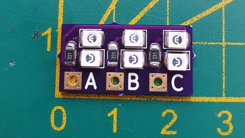
The board is designed to be wired in parallel with a brushless DC motor when hooked up to an ESC. The board packs two LEDs per phase, wired in opposite directions. Thus, current flow in both directions can be visualised on a phase-by-phase basis. If everything is operational, the red and green LEDs on each phase should glow evenly as the throttle is ramped up. However, if there are problems, it will be readily apparent as the blinking becomes erratic or one or more LEDs fails to light at all.
It’s a nifty little device that would prove useful when testing a pile of possibly-defective units. It’s also a quick way to verify a fix. The project is up on OSHPark should you wish to order your own.


It might have been a nice idea to explain what an ESC was, at least once…
I thought it was that key on a keyboard.
Well it’s kinda indirectly implied: “The board is designed to be wired in parallel with a brushless DC motor when hooked up to an ESC.”
An ESC is the the power electronics circuit which lets you use brushless motors properly (in broad terms, I don’t knw exactly either).
Btw. what’s the difference between a brushless DC and AC motor? The article specifically uses “brushless DC motor” but from my limited understanding that’s kinda an oxymoron because one wouldn’t need and ESC if it were a DC motor, wouldn’t one?
I think the distinction has been made because historically many AC motors (such as induction motors) were already brushless at the point in time when electronically commutated DC motors started to become more common. Permanent Magnet Synchronous Motor is the more accurate term.
Sometimes it is also claimed that BLDC is for motors wound with trapezoidal back-EMF, while PMSM is wound with sinusoidal back-EMF. But then what should I call my eBay specials with “I don’t know what that is supposed to look like” shaped back-EMF?
Thanks, but overall it’s still quite unclear.
The Wikipedia article didn’t help neither:
> A brushless DC electric motor (BLDC motor or BL motor), …. and synchronous DC motors, are synchronous motors powered by direct current (DC) electricity via an inverter or switching power supply which produces electricity in the form of alternating current (AC) to drive each phase of the motor ….
-> https://en.wikipedia.org/wiki/Brushless_DC_electric_motor
To me that first sentence implies that only the combination of a BLEM (brushless electric motor) + ESC equals BLDC
Calling any ‘naked’ brushless motor (without electronics) a BLDC is oxymoronic by definition it seems.
not oxymoronic, it’s synecdoche [using a distinctive part of an item to refer to the whole]
a BLDC+ESC [electronic speed control], which in Industrial Terms is a very small lowvoltage/battery fed VFD [variable frequency drive, 3 phase electronic commutator]
The mechanical difference between a 3 Phase AC Motor and BLDC is as mentioned upthread, more in the intended waveform/back-EMF, but that’s not externally obvious.
3 Phase AC Motor: usually refers to a Squirrel Cage Rotor Synchronous Induction Motor
BLDC: usually refers to a Permanent Magnet Rotor Synchronous Motor of design voltage rating < 100v
Altermotor: usually refers to a, modified from automotive-style alternator, Slipring-Energized Wound-Rotor Synchronous Motor, where the kV [thousands of RPM per volt back-EMF] can be varied by the [magnetic] flux strength of the field [rotor winding].
Fun fact: This is how an alternator can control its voltage output without a bucking regulator on the output: by changing the kV strength of the rotor, thus changing the peak voltage output of the 3 phase generator stage of the alternator
Thank you Hyratel – ESC = electronic speed control
Hyratel, is the “100V. Thanks!
Congratulations for explaining the workings of ESC without actually explaining what the acronym ESC stands for.
Electronic Speed Control
Yeah… sorry. kinda broke my own rule there of not including links to relevant parts I’m using.
Like those YT comments pointing to some other relevant video WITHOUT GIVING A LINK, thus forcing every other interested user to search individually, wasting everyone’s time.
But in my defense: I had forgotten the written out version of ESC at the time.
I once looked it up in the past (years ago?) after it was used on another HaD article without explanation… ;-)
https://en.wikipedia.org/wiki/Electronic_speed_control
@HaD: Imho you could use one of those auto annotation systems for acronyms I’ve seen in some forums.
Updated, thanks.
“Electronic speed control (esc)” …..very first sentence.
Mike Szczys’s post right above yours and posted 5 hours before says “Updated, thanks.” because he UPDATED the article with this change.
Electronic Speed Controller.
Why on earth would one use instagram for a project? IG only allows entry if you accept their advert cookies and then it says that I need to register to really see videos. Fsck that site.
I saw a grey rectangle and assumed that someone else would complain for me.
Hah! I have two of those I built with perf boa4d and dual color LEDs where th2 direction of the current chooses between red and green. Because it was so easy to knock a couple together from my parts drawer (3 two-lead bicolor LEDs, 3 resistors, 4 header pins: A, B, C, center) I never bothered making a schematic or real board so bravo to [LouD] for going the extra mile.
Thanks for the article and feature of my little project!
@yetihehe I ofcourse do not use Instagram for my projects, I do use it for posting photos en videos ;)
My project is locatie here on hackaday and on my github: https://github.com/LouDnl/Esc-Phase-Tester
Thanks!
Yeah, that’s my problem. I can’t see your photos and videos. Could you use vimeo or youtube maybe?
Nice, but not that interesting considering LED racewire is the exact same thing, in a better format for frames, and been around for a while…
I considered using racewire for this very purpose. Most racewires on the other hand light up on voltage applied to one wire, amount of power applied and/or only cover only one phase. For problem solving they would be useless unless you use multiple racewires which isn’t very handy.
> fixing failed units is an option
Would you mind elaborating on that? You use this tool, and you can see there’s a problem between phases A and B. I’m with you so far. Then what do you do?
Sure. I use it when I have an ESC that doesn’t work like it should or if I have repaired an ESC and it still doesn’t work like it should.
If an output fails it’s usually obvious because the motor won’t spin. A fail like that can have numerous causes with one or more of the mosfets failing being the most obvious one. I always start with my multimeter and check for shorts on the motor outputs. This usually indicates a failed mosfet. There are numerous videos on youtube explaining how to do that.
It becomes less obvious if after you replace mosfets and the ESC still does not work like it should. Like if a motor won’t spin or starts stuttering/desyncing at higher rpm. I then hook up this little device to see what output has problems. You can do this with and without a motor, but with motor is recommended. The ESC will reset when you apply throttle if no motor is connected. You can still see failing outputs without a motor connected though.
Since there are 6 leds, 2 on each output and 1 per phase (high and low), if one led lights up less, doesn’t light up like the rest it indicates a problem with that phase.
Recently I fixed a 4 in 1 ESC that had broken mosfets. After replacing the mosfets it still had problems, the ESC tester indicated the port and phase. I knew it wasn’t the mosfets as I had already replaced them. But because the lights did not light up like it should I knew that I should look there. It turned out to be 2 resistors that got damaged when the previous mosfets burned out. They had a higher resistance then they should have had.
Thats how I use it.
For me it should also have something which test if both side are open together.