The folks over at the [Barkhausen Institut] are doing research into controlling autonomous fleets of RC cars and had been using off the shelf electronic speed controllers (ESCs) to control the car motors. Unfortunately they required more reliable feedback for closed loop control of the motors, so they created their own open source hardware brushless DC (BLDC) controller.
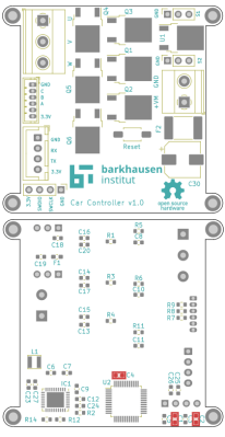
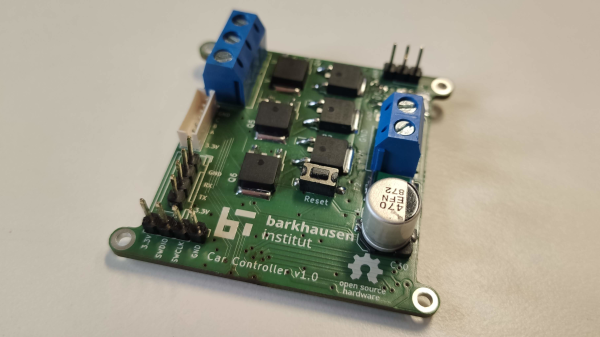
The motor controller they developed uses an STM32 microcontroller that talks to a TMC6140 3 phase MOSFET driver to drive 6 IRLR 2905 MOSFETs. The [Barkhausen Institut] researchers went with the SimpleFOC library as the basis to program the STM32, with installed hall effect sensors indicating motor orientation for their closed loop control.
Designing a functioning BLDC and ESC controllers can be subtle, and their post goes into details about the problems and solutions they came up with to deal with with what was ultimately improper isolation of the MOSFETs interfering with the power rail for the STM32. The source for their BLDC motor controller is available through their GitLab page. For more information on the parent project that uses the BLDC driver, be sure to check out their work on a connected convoy of RC cars.
There’s now a wealth of open source BLDC drivers and projects, many of which we’ve featured in the past, like the Moteus and haptic smart knob, and it’s nice to see other projects explore different options.