In the world of speakers, mass is the enemy of high frequency response. In order to get the crispest highs, some audiophiles swear by speakers in which the moving element is just a thin ribbon of metal foil. As the first step towards building a set of ribbon headphones, [JGJMatt] has designed a compact ribbon speaker made from aluminum foil.
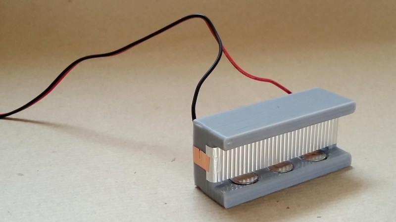
A 3D-printed body holds six permanent magnets, which produce the static magnetic field necessary for the speaker to work. The sound itself is produced by a corrugated aluminum diaphragm made by taking a strip of foil and creasing it with a gear. Aluminum is difficult to solder, so electrical contact is made with a couple of short segments of copper tape. A little Blu Tack and glue hold it all together, and the result is stunning in its simplicity.
Check out the video after the break to hear how it sounds. If you want to try this yourself, it’s important to remember that ribbon speakers have very low input impedances (0.1 Ω for this design), so in order to prevent damage to your amplifier, a transformer or series resistor must be used to bring the impedance up to the 4-8 Ω your amplifier expects.
[JGJMatt] is no newcomer to exotic speaker technology—check out these thin distributed-mode loudspeakers they made! If you’re more interested in recording music than playing it, you might want to read about how a metal ribbon suspended in a magnetic field is used to make incredible microphones. Shout out to [Itay] for the tip.


Awesome! Sounds just like my smartphone!
No-no, sounds like my laptop.
No, it sounds as good as the builder’s phone’s built in microphone.
No, it sounds like Nokia N95… dropped on the tile floor… several times. Nobody talks about the characteristics of this thing. Like how many watts it puts out and how many dissipate into that transformer. The only parameter that is listed into the main article is that 0.1Ω impedance, which I personally think it’s a little eyeballed, rounded up and approximated. I just calculated the resistance for a 60 micron alufoil of that size and it comes out to 0.000047mΩ. The copper/aluminum bonds are usually very problematic because of the aluminum oxide. This can give parasitic resistances which add to the total impedance of the speaker. And finally, the corrugated aluminum loses tension over time and it will drop its elasticity. Thus the volume and the audio profile modifies with time. Just a few thoughts nobody mentioned. I got more.
So you don’t do much with mΩ then eh.
To give you a hint. If you held something that was 0.000047mΩ a foot above this speaker and then let it go then it would crush this speaker, smash through the table and probably break through a wooden floor.
Perhaps you meant 0.47Ω or 470mΩ ? check the math.
I love it!
I remember an old Philco TV commercial explaining how their face colors were “right”,
how could anyone watching another TV know that?
B^)
Sounds better than my speakers, seriously way above expectation.
What an awesome idea! Improve the quality of your own speakers by using them to play sounds recorded from a super high quality speaker.
It’s the same as how you can prove a vinyl record is superior to a CD by making the comparison in a Youtube video.
Very cool. I’ve heard of ribbon mics, but never a ribbon speaker. I’d love to see a characterization of the frequency response. The magnetic field could be strengthened a lot by adding some iron around the outside, I don’t know if that would actually improve the speaker though.
And use copper foil instead of the aly, and you can solder directly to it.
If the goal is to reduce the mass of the moving element Al should be better than Cu, shouldn’t it?
For a given volume of metal? Yes.
For a given physical strength of the ribbon, or a given electrical conductivity? Not sure…
Al is better in this application. Because what counts here is the relationship of electrical conductivity vs. mass. Al has about 2/3 of the conductivity of copper but only around 1/3 of the density. That’s also one reason, why overhead power wires are very often made from Al (besides cost).
Given the size of the ribbon, maybe electrical conductivity isn’t the most interesting property?
It might be better to use a titanium ribbon, perhaps, as it’s lighter and stronger, and can probably put up with elevated temperature much better.
Some decent screw terminals at the ends with brass cup washers would make nice electrical contact.
I would be interested to compare the DC resistance against the impedance at various frequencies. Time to break out the magnets!
Look up the Apogee Stage, Duetta, and Caliper speakers- full range ribbon drivers.
Or Adam Audio studio monitors. Ribbon tweeter and classic cone low/midrange driver
Or THE quintessential full-range ribbons: Magnepan. They sound incredible with decent power, are relatively inexpensive, and are still made in the US.
Magnepans are NOT ribbon speakers. They use voice coils spread over a large surface with a panel full of magnets behind them. It’s a completely different concept.
Ribbon speaks were considered high-end in the 1970s, I think.
That was when my father was very young..
Anyways, they are still excellent. Especially for higher frequencies.
Thanks for the video/writeup! 😎
And now, make a plasma speaker!
My father once saw err heard one in action.
Demonstration was held in a curch, I think.
The result was phenomenal, he said.
They are typically only for tweeter. Brands like RAAL have a very high reputation. There have been a few full range ribbons but those are $$$$$$
One word: Magnepan.
One word: Nope.
Nice design! But I do wonder how he made the electrical connection between the aluminium foil and copper foil? If the total impedance of this speaker is 0,1 Ohm, conductive adhesive (available on copper tape) probably is not sufficient? Or not for long, at least.
considering the design, it’s probably getting a combination of conductive and capacitive coupling from the copper foil through its adhesive to the aluminum, ESR notwithstanding. if the coupling is good enough, the AC impedance can be lower than the series resistance
What direction are the magnets facing? Neg up or down?
Doesn’t matter as long as all magnets (upper and lower) have north in the same direction (down or up). It also matters when you have two magnets that they are the same direction in both speakers (if not, you need to change polarity of cables).
Magnets don’t have negative and positive.
Those are not magnetized along the long axis, but along the thinnest axis. The field must cut across the foil. So both sides should have N to the right, or both to the left.
I wasn’t clear. I mean the magnetic field must cut across the foil, at 90 degrees to the direction of current flow. So bar magnets are better, and one should point North towards the foil, the other should point South towards the foil.
Is it sitting on a cardboard box (acting as a resonance chamber for bass)?
I wonder how orientation, placement and number of the magnets would effect this. Like what if you put magnets on the opposite side as well? Should the polarity of the magnets swap back and forth? What if you used smaller magnets but more of them? What about many bar magnets instead?
He put magnets above and below ribbon. What you want is parallel magnetic field lines in area where your ribbon is. So magnets below and above ribbon should have north in the same dircetion. Also magnets only on one side of ribbon will work very poorly (ribbon will try to twist). Smaller magnets or one big magnet will work about the same, but one big magnet (on each side) will give you slightly more power (almost unnoticeable). If you use bar magnets, they will behave as single big magnet.
Why not use Halbach array?
https://en.wikipedia.org/wiki/Halbach_array
Because you need a linear field that goes from top to bottom, across the ribbon.
This would surely be much better in a U-channel of mild steel, with holes drilled in the back to allow more air movement.
Apogee Scintilla are notorious 1 ohm load loudspeakers. I’d love to see an article on more dead short loudspeakers.
You should check out Joppe Peelen Channle https://www.youtube.com/channel/UCeBox1lGM29f72KL2KrDm7A
He has been building ribbon speakers for the last 3 + years A very great resource in the DIY community
Any suggestions around building a transformer to try with this (as opposed to using the resistor)? I have random RF toroids sitting around from HF experiments, not sure what material would be good (or how much it matters here just for experimenting).
Now make it an integrated part of a tinfoil hat and kill 2 birds with 1 stone!
The Heil air motion design was a different approach to this. Anything to get the efficiency up helps. The naked round magnets for example; a flux circuit that has only the ribbon in one concentrated gap is best. Those Heil’s had a lot of steel laminates making up the flux poles. Modern magnets would decrease mass but iron pole mass would mostly remain the same. Awesome sound, I have a pair. Two third’s of the spectrum 20K on down out of a single driver. No crossover in that whole range. Efficient!
Pardon m’y ignorance here folks, but I have a basic question. My understanding is that the foil is made to vibrate and produce sounds based on variation in a magnetic field. But Aluminum is supposed to be non-magnetic, so how can it vibrate due to magnetic variations?
You run current through the aluminum foil, and it’s the current making a magnetic field that pushes on the permanent magnets. This is a pretty small force, so you’ve got to have a pretty light membrane, and that’s why this sort of thing is usually limited to tweeters. (But see Magnepans. Best speaker for the money, if you like their sound…)
Speakers are always like strange linear motors, if you think about it, with (traditionally) a speaker coil that pushes against a permanent magnet in the center. Here, the coil isn’t wound up.
You are invoking two magnetic fields, which is over-complicated..
The simpler explanation is that the static magnetic field acts on a moving charge.
If you pass a current (the moving charge) through the foil it experiences a force perpendicular to the field and perpendicular to the motion, and that force acts on the ribbon, because the current can’t jump out of the ribbon.
https://newatlas.com/graphene-speaker-non-vibrating/49376/
Checkout the graphene speakers to go deeper in math and throw almost all calculus with other materials…