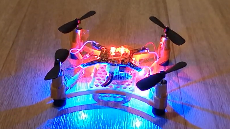
Quadcopters are fantastical things, and now come in a huge variety of flavours, from lithe featherweight racers to industrial-grade filming rigs worth tens of thousands of dollars. The Beatle-1 from [masterdezign] comes in at the smaller scale, and its body was created entirely in code.
To create the Beatle-1, [masterdezign] used OpenSCAD, a 3D modelling program that uses code rather than visual tools for producing geometry. Thus, with a series of Boolean operations, extrusions and rotations, a basic lightweight quadcopter frame is created in a handful of lines of text. Then, it’s just a simple job of 3D printing the parts, wiring up four Olimex F1607 motors and hooking up a flight controller and the little drone is ready for takeoff.
The Beatle-1 serves as not only a fun flying toy but also a great example of applying OpenSCAD modelling techniques to real-world applications. Parts are available on Thingiverse for those wishing to roll their own. 3D printed drone frames are popular, and we’ve seen a few around these parts before. Video after the break.


I admire the patience of anyone who can actually design anything real in OpenSCAD. I used to use it before Realthunder’s FreeCAD assembly3 got really good…. And I don’t think I’ll be going back anytime soon!
Not as hard as it looks, just takes some patience: https://i.imgur.com/5rGyQqy.png
For some of us it’s a lot easier than a GUI. I’ve never managed to get the hang of any GUI CAD program…. Just figuring out how to move something in 3D is really hard. But in code, it’s all much simpler for me.
That enthusiasm might be short lived when you need to add a chamfer around an edge.
Not actually that difficult, you can create spheres with your chamfer radius, tranlaste them to the 4 corners of a cube and then wrap a hull around them. Subtract this from a another object and you have internal chamfers.
It depends on the edge. Sometimes it’s relatively easy. Sometimes one can do without it. Sometimes it’s harder.
You do have a point (or should I say radius?) there. Fillets and chamfers are a lot of work to do in OpenSCAD. Maybe one day the clever folks who work on improving it may consider adding support, I can only hope.
when it’s not native to OpenSCAD, someone will have created a library for it:
https://www.thingiverse.com/thing:1305888
that is how I was too and attempted FreeCAD and Blender twice. Then someone spent 1 hour each week walking a bunch of us through the basics of CAD using Fusion360 and after 6 weeks it was enough for me to start making some models on my own. Then AutoDesk does what AutoDesk does and I bailed and switched to the beta 0.9.2(?) of FreeCAD and was stunned at how well it worked and how much of what I learned using F360 applied to FreeCAD. And it was the fillets and chamfers in OpenSCAD which made me want to use a GUI CAD too. But guess what, there is OpenSCAD support in FreeCAD!
Nice. Thanks for sharing.
Sadly it’s limited, eg. svg imports in openscad don’t make it into freecad. But I can totally see me using both together.
The nice thing with FreeCAD Assembly3 is you only have to think in 2D sketches with everything determined by constraints, you never directly move anything, but it’s still interactive and doesn’t require you to be able to imagine 3D operations in your head(or use trial and error) like OpenSCAD does.
As other replies have said, it really can be easier than selecting, pulling, prodding shapes off a menu which itself varies depending on what CAD program you’re using.
For me there’s more a sense of permanence to an OpenSCAD script than say a FreeCAD file format. In 100 years “subtract 20mm dia cylinder from 50mm cube” is still going to mean exactly the same thing it does now – even if OpenSCAD were itself to disappear, the model can still be built from first principles.
As for designing real things with it, my OpenSCAD models have clocked up thousands of downloads on Thingiverse which I figure is testimony to their usefulness.
Also I had a 100-tooth involute gear profile DXF generated from a gear webpage I tried to import into FreeCAD, and it just hung. OpenSCAD had no trouble.
I feel that OpenSCAD is more easily understood if you have an aptitude for programming.
Problem with OpenSCAD is not that you describe models in a language, that’s an advantage.
Problem is that you can’t reference any generated geometry in that language!
You can’t even do simple things like ‘give me a bounding box of this complex model, so I can create a box for it’.
To make a box around any openscad model, just do hull, then minkowski with a sphere (adds a bit all around), then subtract the hull. Bingo. Shell that fits perfectly, whatever thickness you want.
If you design your complex shape in a module, you can just subtract it from any other shape. You can scale it before subtracting to make the box as snug or as loose as you want.
Which part of “Some of us” didn’t you understand?
For the ones that like to “program” 3D structures:
https://github.com/McGyverItaly/3D-OpenSHuFFle
3D-OpenSHuFFle is an OpenEuphoria program that creates complex OpenSCAD polyhedrons starting from a text file.
It contains the +NACAxxxx 4-digit section type, that simplify a lot to design propellers, wings of airplanes, helicopters etc.
I took a look at that Github page, and there’s no example of what the thing does, or produces. A screenshot or two would be nice. Which is something I _do_ want to know about, considering the download content there is some mysterious executable and a few zip files.
Similar: I’ve been playing with CadQuery (https://github.com/CadQuery/CQ-editor#readme).