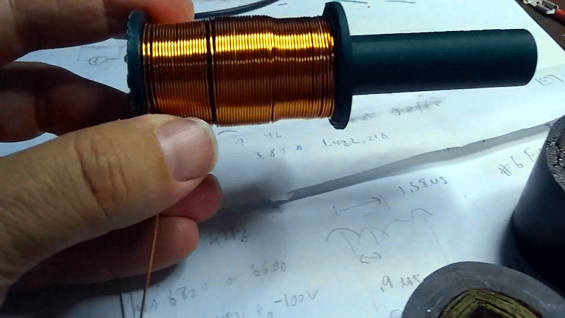
Inductors are not the most common component these days and variable ones seem even less common. However, with a ferrite rod and some 3D printing, [drjaynes] shows how to make your own variable inductor. You can see him show the device off in the video below.
The coil itself is just some wire, but the trick is moving the ferrite core in and out of the core. The first version used some very thick wire and produced an inductor that varied from 6 to 22 microhenrys. Switching to 22 gauge wire allowed more wire on the form. That pushed the value range to 2 to 12 millihenrys.
What can you do with an inductor? For this type of inductor, you are usually interested in resonating a capacitor either for an oscillator or a filter of some kind. You see big roller variable inductors in antenna matching circuits, but it is doubtful that these inductors would be suitable for transmitting unless it was with very low power.
There are many ways to measure inductance, especially so today. The video shows an LCR meter and network analyzer. But it is easy enough to use a simple LC oscillator and measure the output with a scope or use a grid dip oscillator if you happen to have one. In the vein of making things easier, though, we really wanted to see [drjaynes] build a coil winder if he plans to make many of these.


Variable inductors are easy. Wind the coil on a coil form, and then a core of something moves up and down. So the coil form might be threaded, and a powdered iron core (threaded on the outside) goes up and down. That’s a typical IF transformer. At UHF, the core might be brass.
None of that is hard (though maybe finding cores these days is harder). The real trick is if you want this controlled by a knob on the front panel. Turn the knob, and it will move in and out from the panel. Messy.
So it takes much more mechanical work for the knob to stay flush with the panel as the core goes in and out of the coil form.
Car radios used to be inductively tuned, so I once built on oscillator around a coio from a car radio, leaving the mechanism but rewinding the coil for my needs.
People did make them, and wrote about them, and the obvious place to find them is old magazines.
There is a variable inductor design, with air core, that works like an autotransformer. There are two coils wrapped on two formers, one is inside the other. They are connected in series, and one can rotate in relation to other. When they are “in phase”, they have equivalent inductance of coil made of sum of the turns of component coils times the coupling factor. When the coils are at 90 degrees to each other, the inductance is roughly equal to sum of inductance of the component coils. When the coils are rotated 180 degrees relative to each other, the inductance is equal to inductance of coil made number of turns that is difference between number of turns of component coils times the coupling factor. In theory one could make a variable inductor that has value of 0 at the 180 degrees position…
That would be what they used to call a variometer. Now the word has been hijacked and means something else.
Since the inner coil is smaller, I’d think adding just a few extra turns could get it pretty close to zero inductance, relative to the maximum inductance. Oddly, no 3D printable designs out there.
There are pictures of some variometers that were made by Elmer Osterhoudt of MRL. No construction details though.
just make the knob stay still. https://hackaday.io/project/177163-a-cheap-compact-linear-slide
Can also insert a copper rod into the coil to reduce the inductance. A little lossy perhaps, but maybe handy? Cryogenically chilled silver would work even better but perhaps not handy.
And more fun, “accidentally” test it with a higher current and launch the ferrite rod across the workshop. Or much higher currents and fling the frozen silver rod.
IIRC (it’s been along time), ferrites come in different “alloys” suitable for different frequency ranges — there’s not one “universal” mixture that will always work.
No idea if I am the only one to do that … but when I review papers I always (minorly) critique mixing different SI prefixes for the same thing. It’s definitely not the end of the world, but it’s a service to the reader.
> from 6 to 22 microhenrys
> to 2 to 12 millihenrys
here it’s kind of obvious because the increased values are numerically smaller (which is why I noticed and not over read it) … but I would argue that it would be better written as:
> from 6 to 22 microhenrys
> to 2000 to 12000 microhenrys
making the change obvious immediately
It’s already obvious, because of words. You have a preference and that’s fine.
heh i also had to double take to read it right but i wasn’t put off by it. i’m not crazy about writing 2000 microhenries, though. oddly, i find uH and mH easier to differentiate.
(cue u ain’t mu)
Please do the needful!
I was trying to remember where I saw a large motorized variable inductor.
It may have been at an Omega broadcast station*, changing the inductance while transmitting.
*LaMoure, ND
https://www.globalsecurity.org/military/facility/lamoure.htm
A guy told me you could make adjustable VHF inductors with a drinking straw, magnet wire (obvious), and certain sized and material screws (that you use as the core). I had so-so luck. I couldn’t get the screw to change the inductance all that much. If I did it again, I’d use a thicker type of straw and I guess buy a bunch more screws and select the most ferrous. Why all this trouble? Well, because the Toko brand coils that were used in this area have been hard to come by for years (unless someone has now taken up the slack…).
The problem with using ferrite screws:
The ferric properties increase inductance.
The conductive properties decrease inductance.
There is a reason why ferrites are made of iron oxides and specifically made to be nonconductive.
I did the same experiments.
You can make a pseudo variable inductor with a variable capacitor and a quarter-wavelength piece of transmission line. Your pseudo inductor might have a higher Q factor than a real inductor!
But often, people move to variable inductors because variable capacitors are hard to get.