Usually when we post a Fail Of The Week, it’s a heroic tale of a project made with the best of intentions that somehow failed to hit its mark. The communicator that didn’t, or the 3D-printed linkage that pushed the boundaries of squirted plastic a little bit too far. But today we’re bringing you something from a source that should be above reproach, thanks to [Boldport] bringing us a Twitter conversation between [Stargirl] and [Ticktok] about a Texas Instruments datasheet.
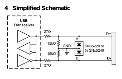
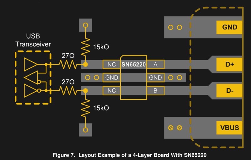
The SN65220 is a suppressor chip for USB ports, designed to protect whatever the USB hardware is from voltage spikes. You probably have several of them without realising it, the tiny six-pin package nestling on the PCB next to the USB connector. Its data sheet reveals that it needs a resistor network between it and the USB device it protects, and it’s this that is the source of the fail.
There are two resistors, a 15kO and a 27O, 15k ohms, and 270 ohms, right? Looking more closely though, that 27O is not 270 with a zero, but 27O with a capital “O”, so in fact 27 ohms.
The symbol for resistance has for many decades been an uppercase Greek Omega, or Ω. It’s understood that sometimes a typeface doesn’t contain Greek letters, so there is a widely used convention of using an uppercase “R” to represent it, followed by a “K” for kilo-ohms, an “M” for mega-ohms, and so on. Thus a 270 ohm resistor will often be written as 270R, and 270 kilo-ohm one as 270K. In the case of a fractional value the convention is to put the fraction after the letter, so for example 2.7kilo-ohms becomes 2K7. For some reason the editor of the TI datasheet has taken it upon themselves to use an uppercase “O” to represent “Ohms”, leading to ambiguity over values below 1 kilo-ohm.
We can’t imagine an engineer would have made that choice so we’re looking towards their publishing department on this one, and meanwhile we wonder how many USB devices have gone to manufacture with a 270R resistor in their data path. After all, putting the wrong resistor in can affect any of us.


k for kilo is lowercase. Uppercase K is Kelvin.
In the context of electrical schematics, there is no unit Kelvin for this to be a distinction. K means kilo regardless of case.
If you don’t think case is relevant then I’d like to you build a 10MW/100mW 5V power supply.
Today I learned that resistors in 10MW power supplies are specified in Kelvin as well as Ohms…
He said k will meak kilo in an electrical schematic, regardless of case. He did not say case doesn’t matter in general in electrical schematics.
I have to disagree. Temperature is often listed in Kelvin in components and schematics, like mV/K. Switching k with K can lead to some funny mixups.
similar to some people, claiming to have 100mbit/s internet :-)
I always find really stupid when people argue, that the case would not matter.
That unfortunately depends on when and where you learned that – I grew up in Denmark in the sixties and seventies.
In my childhood we learned that Capital Letters meant a positive exponent and a Lowercase Letter equals a negative.
Example M = Mega (1E6) and m = milli (1E-3) – unfortunately not the same exponent, but D = Deca (1E1) and d = deci (1E-1) works better. It had been that way for centuries here, but electronics and Computers kind of changed some of it.
Properly educated children all know that the Latin exponents are upper case and the Greek exponents are lower case. Why else would French intellectuals chosen such a system for their new metric?
Yep. And it’s kilohms, megohms, etc., when spelling them out and there are adjacent vowels.
Standards exist for a reason, and I’m shocked to see a manufacturer like TI fail so badly here.
Your trying to sell internationally accepted SI units to a country that still uses feet and inches.
You would have better luck selling fridges to Eskimos.
Thanks to climate change, Eskimos are the final untapped fridge market.
Eskimos were very appreciative of fridges – they kept food from freezing.
Isnt there a convention (probs not relevant to schems) to use k for 1000 and K for 1024 ?
If it’s a resistor symbol, we know it’s “ohms”, so no need to add the omega, or “O”.
Probably a case of the wrong font used for acrobat conversion. Anyone familiar with USB specs would notice the value to be outside of the range of the usual ranges for driver impedance anyway.
Or the office intern supervising/reviewing the OCR from a faxed original.
Plenty of us are building these things without knowing the correct impedance. We might be very familiar with the digital side of the USB specs, or we might be using existing libraries and building a cool thing that hangs off USB. I’d imagine there’s a few people burnt by this, though I did spot the O wasn’t a zero… but I’m a designer, so I’m good at spotting font issues.
Your typical Ethernet cables is around 100 ohms while USB has a typical impedance of 90 ohms. You don’t need to know the exact value, BUT someone with some experience would know rough ranges. Always a good idea to understand datasheet/spec of what you are building. Even if you don’t, a bit of common sense for electronics helps a lot too. It give you a rough idea of what to expect.
That’s what separate a noob from a grey beard.
The single ended driver impedance is around 45 ohms. So 27 ohms is within the same order of magnitude of what’s to be expected while 270 ohms is an order of magnitude higher.
BTW if you are doing a PCB layout for USB, you would at least know what impedance for the track that you are trying to achieve. Don’t tell me that it is not iun the app notes or datasheet.
It’s not “best practice” but I have had plenty of projects work Just Fine with USB tracks laid out “close together” and “about the same length” with no further optimisation. This is for serial over USB 1. It probably won’t with high speed video! Your mileage may vary etc etc :-)
Also, not a font issue – greek letter have a separate section of Unicode. OΩ. Same font.
Decades ago before Unicode people switched fonts to get non-Latin characters but that’s not something anyone should be doing now. This is a human error.
I agree… you even have the composite font system where if your font DOESN’T have a particular symbol, it can fall back on symbol libraries. Think of any time emoji are used directly (I’m not counting sites like Facebook that intercept them and replace them with images). There is rarely-if-ever a custom emoji set to go along with switching from Arial to Comic Sans or whatever.
Have seen ‘W’ before, presumably as a font substitution artifact; Symbol contains respective Greek letters in this range. It’s not even that nonsensical, at least if you realize they’re not talking about watts (because, watts at what resistance, one doesn’t matter without the other–ohh), and think of phonetically spelling it as “owms”.
I was thinking more like this was some sort of scanned document which failed at the text recognition…but what do I know :)
My assumption is that their people know what they were doing and it was misinterpreted by a machine.
Agreed. The TI datasheets are usually pretty good.
A rule of thumb for me is that my trust in a datasheet or applications note diminishes with time (and the number of company name changes). Meaning that, nowadays, the company whose name is on the data sheet is much less likely to be the company which employed the original designer of the part/author of the app note.
1st commandment: Never mix ‘0’s and ‘O’s. (And l/I etc).
That’s why you’re supposed to put a strike through your zeroes. Except in countries where the stike is for “ohs”.
I never strike my 0’s – I dot them, thus preventing confusion with Ø for diameter. I was taught the R1k2 notation principle and never looked back ;-). Besides, what is ‘ohs’? ‘Ø’ means ‘island’ around here.
Thats an ö here. Funny I’ve never though until now the possibility for confusion between the crossed zero and the Dansk/Norsk island.
I swear that’s the reason some old terminal fonts put a dot in the middle of the O.
Early terminal fonts were fixed 5×7 pixel character cells. You couldn’t make the zer0 narrower than the O without the zer0 being so narrow that it looked out of place. The simple solution was to put a dot in the middle. Even a / though a zer0 looks out of place in a 5×7 cell
Yikes. Could happen to the best of us. I was always taught to put a space between a number and its unit, which would have helped make this less ambiguous, even in the event of an Ω to O font fail.
That’s not a font fail. Greek letters are in a separate section of Unicode.
In older fonts, like “Symbol” https://en.wikipedia.org/wiki/Symbol_(typeface) used by old Word versions, they are in ascii section. But even there it is W and not O.
Yes! Use spaces! I’m getting tired of my phone and browser telling me I “meant” to type 500km instead of 500 km.
Luckily, he didn’t mean to say “Input Impedance 27 Ohm”, otherwise someone could use 11270Ω resistor.
The O is clearly wider than the 0, though, and the 15kO makes it clear that it was not meant to be 0.
Except that “15k0” is a commonly used shorthand for “15.0 kΩ,” indicating a 1% tolerance or better part, while “15k” would be used where looser tolerances (typically 5%) are acceptable, unless the tolerances are specified separately.
In general, the 1%/2% resistors are specified on their package with 3 significant digits. e.g. 15.0K or 15K0
while 5% or worse are specified with only 2 significant digits. i.e. 15K
3 significant digits = 4 numbers/color rings whith 3 for the value and 1 for the 10^x multiplier
2 significant digits = 3 numbers/color rings whith 2 for the value and 1 for the 10^x multiplier optionally tolerance
USB spec have a very very loose tolerance for the pull down resistors. There was a ECN to loosen the pull down with an allowable range of 14.25K to 24.8K probably because of poor tolerance inside a chip. So you would expect to see only 15K (2 significant digits) specified.
ESCHEW OBFUSCATION!
Your schematic should include a note indicating “all resistor tolerances are 5% unless otherwise marked.” Any 1% or 0.1% resistor would then require the value and percent symbol. No ambiguity there.
27O is just bad form. You should never include the letter O, either use no letter after the numerical resistor value, or use the omega symbol, or write out “ohms.”
I would hope 15k 1% or 15.0k 1% is how one would document that part in their schematic.
Basically right, but I would do it the other way round:”…1% unless otherwise marked”. Less resistors to mark. But we write the % to any resistor, so its unambiguous.
Not so. 15k0 specifies an accuracy too.
Tolerance :)
No it doesn’t.
It does not distinguish between 1%, 0.1%, 2%.
Not in general. Only if you state that convention on the schematic
Yes, if you’re 25 years old, have 100% eyesight, and are looking at the magnified picture above this article, then you’re completely right. :P
When I’m scribbling down alphanumerics, part numbers, codes etc, I strike my zeroes to make them unambiguous. Typed or printed you just have to guess on width.
Same. I also put lines under certain letters and numbers to avoid mixing up 1, l, 6, b, etc.
I’ve seen TI screw up stupidly a number of times. One that comes to mind: A whole app note, where the engineer was showing designs for phono RIAA networks. Except…he thought that the asymptotic graph that is sometimes used to define the filter response was the actual ideal response, and that his preamp would keep improving the closer he got to it, which he proceeded to attempt to do!!! I couldn’t believe it.
oh man. I once had a datasheet of an 9dof ic in qfn package where the pinout was shown bottom up in stead of top down. of course the first pcb had that ic mirord and i had to attach it dead bug style to get it working…
I have some vague memory of that *precise* thing happening to me as well…
I remember discovering that the TMP36 is awfully tolerant of abuse that way. Some dick decided that the TO-92 pins should be drawn from the bottom view, because sensible datasheets are just too boring I guess, which reverses V+ and GND. Got hot enough to burn my fingers on the plastic, but that same part worked fine after being flipped around the right way.
I had a MEMS sensor too in LGA-12 package (LIS2DH12TR) . Since i soldered it by hand and glue it dead bug style on a protoboard i took special care of the pinout in the datasheet. It was a relief to see it was drawn bottom-up, which was then quite simple to wire. So, success on the first try. But i had surprises so often that i always verify many times this kind of information.
Ha! Don’t forget “micro” – I’ve come across “µ” being subsituted with “m” in documents quite often.
In very old documents “µ” is denoted as “mm” to make the confusion complete.
A relic from the olden days also seems to be “mFd” for “µF”.
Substituting µ with m is just abhorrent… Since m is already occupied for milli.
The correct substitute is u for its similar appearance. Though, one can just use a keyboard layout with µ on it. If one does electrical engineering it is nice to have, Ω for that matter as well.
Otherwise one can just stumble over to Wikipedia or the like and search up the symbol, it is fairly trivial to be fair. (Searching “micro” or “ohm” gets one there fairly instantly.)
If you don’t have a keyboard that can do the Ω symbol, just press alt + 2,3,4 on the numpad.
There’s your ohm.
That doesn’t work reliably anymore. The default code page is changed with the regional settings. Yes, code pages still exist, they’re just buried so deep in the OS that you wont find them.
+10 though, for pointing out a BIOS feature from the 1980’s that still functions.
It isn’t the keyboard that defines what you can type.
It is the keyboard layout file, this one can edit to contain any character one desires.
Ie, one can place Ω as an alt version under O, and µ as an alt version under U. (Though, I have µ under M myself, since it is part of the Scandinavian keyboard layout.)
Remembering where one put what characters in the layout is though a different story. But that is like all other short commands one has to remember.
It is however easier to remember when it is printed on the keycap on the physical keyboard. But the keyboard is nothing more than a matrix, one can take whatever layout file one want and run with it.
Exception to a few layouts that expect certain keys to be swapped in the matrix…… These layouts one has to edit to actually have them work properly on keyboards not built for that layout. And yes, keyboards built for the layout will not work properly with most other layouts…. Since that is what happens when one physically changes the key matrix, instead of just changing the layout file. (Though, this is a remnant from the “good old days” when keyboard scanning were more hard coded, ie, one couldn’t just change the layout file.)
Under Windows I have used charmap extensively for the last 30+ years or so when writing technical documents that need symbols.
Anybody know if there is a cool Windows widget that can simplify the process of going to google/wikipedia, searching for the symbol, then copying and pasting? I know you can use alt-codes… thats more codes than I’d like to memorize though, and having a printout taped to the wall next to my monitor is just so 90’s. I’m picturing something that looks like the symbols menus in MS Word, but that could be pulled up with a hot-key, and clicking the symbol copies the character to the clipboard so you can paste it into any application.
If there isnt anything like this, I may just whip something up in processing some day when I want to procrastinate all the things I need to do.
The character map app does all of that with maybe a click or so extra to what you described. It’s been there at least since win 95. Still has the win 95 look to it. I think it’s charmap.exe.
Even worse: a capacitor of 10µF marked like 10 MFD Of course I would not mind a capacitor with Megafarads of capacity.
What ever happened to nF? Is it just old people like me that still use nF?
Nope, totally an engineer that did it. Not only that, it got through all sorts of review processes from people that should have known better. This isn’t just pie on the face of one fella in that company, it’s a whole gob of em.
They often missed typos in datasheet. I have proof read NDA prereleased datasheet and found mistakes for one company and found wrong math in another. I am not even trying to find them but found them while skimping through.
The math makes no sense as the units are wrong. It is the beauty of dimensional analysis – you can spot mistakes even when you don’t know enough about how they come up with the equations.
That is what proof reading is for.
But what is your point?
It’s a discussion about mistakes in datasheets. Not every experience ends with a moral.
Proof reading is *hard*. Humans suck at vigilance tasks in general.
Unless it’s on the internet, of course, where there’s a horde of people falling over themselves to complain about typos and grammatical errors. It’s hard for one person to find every error, but easy for a thousand or a million people to spot one.
It’s particularly hard to find errors in your own documents. You know what you _meant_ to write and that’s all your brain will see. Until after you’ve gone to print and see the distribution copies….
Personally I follow the system to use the magnitude as the decimal point. And then use E for when the exponent is 0.
Ie, 1K2 is 1200 ohms.
27E is 27 ohms.
And E05 is 0.05 ohms.
Resistance values rarely gets much bellow singular ohms unless it is a huge shunt resistor with multiple terminals, and these are rarely in the Mega ohm territory, so should be fairly safe to write 25m without creating confusion for far larger resistances.
The component symbol itself is what identifies the fact that we are talking about resistance, making Ω and even R as fairly redundant. All though always nice to see them regardless. If one doesn’t know how to type Ω, then type R instead. (or one can go to Wikipedia and just copy paste the correct symbol, it is trivial to find…)
Using the correct symbol for resistance though gets more important if we also write other properties of the component, like parasitic capacitance, inductance, voltage rating, current rating, max continuous power dissipation, etc…
All though, if one has little electrical engineering knowledge, then this is all black magic nonsense regardless. So mistakes can creep in fairly trivially.
BTW I think someone should make these type of things as interview material… i.e. Spot the mistakes in a schematic or even guess the missing number/color on a resistor on a board that was discolored/missing. The latter is quite often what you might find trying to repair something.
A person know the order of magnitude of what the value should be is way ahead of one that doesn’t.
With repairing old circuit boards, it’s not always that simple.
For example: mains switching control boards – I have never seen a faulty SCR on these boards … though many times, I see the three remaining legs.
I blame the adults. Seriously, who invents a language where O and 0 are indistinguishable and 5 and S are indistinguishable when hand-written? And don’t get me started on I and 1.
like if you happen to live on 1151 S 1st street good luck ever getting a postcard.
in the meantime it’s 27r
But this does remind me of a certain datasheet inconsistency that caught me out – every single datasheet I’ve ever read shows the pins with the top of the chip oriented up. Except 1 audio chip that I’ll never use again. It shows the pins from the bottom.
Seriously, who would do that?
If S and 5 are indistinguishable… you are writing one of them wrong! 5 has straight edges on the top and left… S does not!
If I and 1 are indistinguishable, again you’re doing it wrong… the top of a 1 looks like a half-arrowhead, an I does not.
If O and 0 are indistinguishable, your zeros are too fat and need a diet or your Os are too skinny! If you can’t adjust the width of either, a dot or stroke in the centre of a 0 is a reasonable compromise. Some fonts do the stroke (e.g. Terminus) others do a dot. Unless you’re writing in some Scandinavian language, Ø also works for 0.
Well, I only got a C in the Lettering unit of Drafting 101, so I always slash my Zeros, Sevens, and Zeds. And I put serifs on my Esses to distinguish them from Fives.
I’m old enough to remember kilocycles per second (kcps or kc/sec) for frequency, mfd and mmfd (pronounced “mickey-mikes”) for microfarads and picofarads, and the unit of conductance was the mho. Reader of documentation for vintage Hollow State circuits, beware.
The medical community still seems to use “mcg” for micrograms, unlike us engineers who switched to U for “micro” a few decades ago. Every time I see it, I think to myself “what’s a milli-centi-gram, again?”
Maybe you’re just reading them wrong.
While we’re whining, I hate when on a datasheet, application note or schematic, there’s a bunch of lines 5-20+ brought to the “box” that is the chip, in a close spaced parallel block like a bus, then you squint at the tiny pin numbering by each one and it goes 14,5,9,1,19,2,4,3,11 …. and you have to look each one up on the pinout too. I’d rather have it all crossed up, wires going to the box in sequential order. … Some are more evil than that… go 1, 3, 5, 7, 8, and you think you’re not using pin 2, but there it is on the other frigging side, 9,10,2,12,11.
that datasheet talks about the part not being suitable for high speeds of USB2.
Note in the page header suggests it is from 1997, with a review in 2015.
I was scrolling down to see if anyone had pointed out that the resistors are built into the tranceivers since like, the 90’s.
military uses written zero as Ø so as not to order the wrong part
That won’t work for the Norwegian military.
what a mess….Norway is a member of NATO
+1 for the old CRT ANSI/ASCII text font where a “zero” has a crosshatch to differentiate it from the uppercase “O”. I never liked it when Unicode deleted this feature. I still write zeroes like this for my own peace of mind.
Look ma, I’m in a Hackaday article.
:)
I create the designs and then often manually produce a prototype. Then… later when there is a small batch run, the intern gets to assemble things. That’s when things go wrong.
Also the professional assembly factory did this to me once: I specified 27Ohm and they mounted 270R. Yup. I’ve learned this the hard way….
I recommend not writing ohms at all.
Either use Ω or an R, since non of those can be confused for a number nor a magnitude.
Though, in a lot of cases, the resistor symbol itself will be all the information needed, so even stating that it is resistance can be redundant. Not to mention that the component specifier should already contain an R. (As in R42, for the 42nd resistor on the board.)
And I personally write all values with the magnitude as the decimal point, E for when there is no magnitude, like 470E for 470 ohms. Or 1K2 for 1200 ohms. (Also note that I don’t write “Ohms” but rather “ohms” since a capital “O” is a lot closer to 0 than a lower case “o”.)
I also follow the standard of writing all positive magnitudes with capital letters. Except for k in some cases. (Since people seem to get confused when one writes Kg at times. And some confuse capital K for Kelvin, even if temperature is not even relevant in most cases. Writing 120K for a resistance value is obviously not relevant to temperature.)
NIST’s SI unit style checklist might have helped here, especially rule #15: https://physics.nist.gov/cuu/Units/checklist.html
It should be mandatory reading among anyone writing technical documentation.
ugh! O for ohms! never seen that one before.
personally, i write out “ohms” or i leave it off entirely, nothing in between. if you see “R1=27”, you’ll be able to figure it out. or 27 written over the zigzag line.
It seems like revision F of that datasheet have the proper greek Ω sign, but likely using a different font than the rest of the text, but sometime between July 2004 and May 2015, the general look of the datasheet and illustrations was updated, and something went wrong.
Yeah TI seems to have “modernized” a lot of their datasheets, which broke several, fundamentally, and they’ve not come around to fixing this. I’ve tried to contact them, but their “report wrong documentation” contact method didn’t work. Many of these Datasheets seem to have a 2017 copyright.
This is my least favourite, the TPA3137D2:
https://mobile.twitter.com/denergy_dtime/status/1211232419799547904
I don’t know what happened, whether they tried to OCR-automate conversion of datasheets to some new template, or outsourced that to the lowest bidder without any quality control.
I’d bet it’s the same engineering co-op student at TI who slapped that fugly, WAY-oversized first page on ALL National Semiconductor datasheets that read, “National Semiconductor is now owned by Texas Instruments,” right after TI bought National. Either TI isn’t/wasn’t paying their co-op workers enough, or they are/were not checking their work.