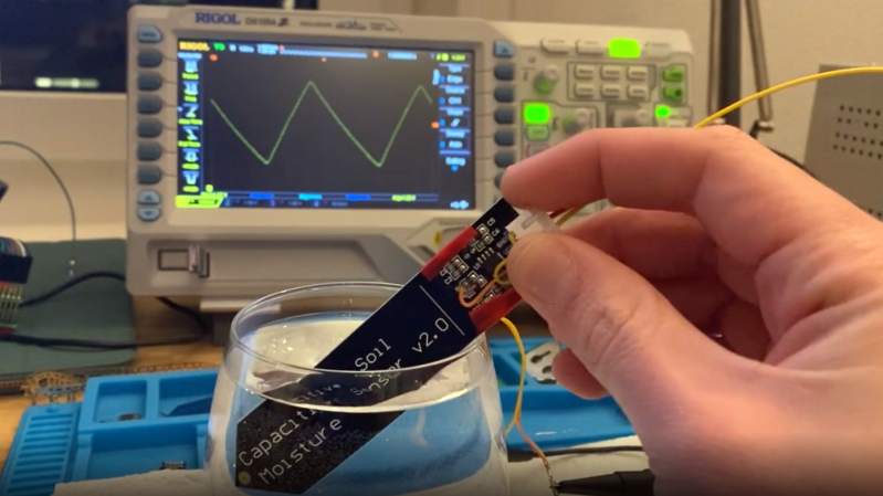
In a way, the magic of a soil moisture sensor’s functionality boils down to a simple RC circuit. But of course, in practice there is a bit more to it than that. [rbaron] explains exactly how capacitive soil moisture sensors work simply, clearly, and concisely. He also shows, with a short video, exactly how their output changes in response to their environment, and explains how it informed his own sensor design.
 At its heart, a moisture sensor measures how quickly (or slowly) a capacitor charges through a resistor, but in these sensors the capacitor is not a literal component, but is formed by two PCB traces that are near one another. Their capacitance — and therefore their charging rate — changes in response to how much water is around them. By measuring this effect on a probe sunk into dirt, the sensor can therefore indirectly measure the amount of water in the soil.
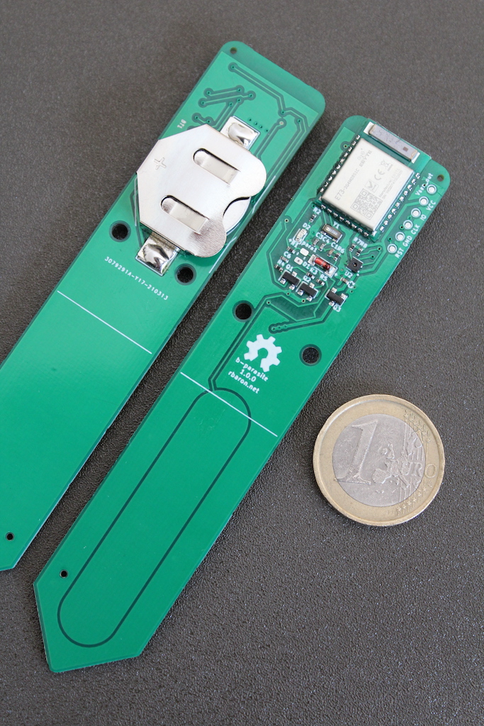
This ties into his own work on b-parasite: an open-source, all-in-one wireless soil moisture sensor (which was also a runner-up in our Earth Day contest) that broadcasts over BLE and even includes temperature readings. One thing to be mindful of if you are making your own PCBs or ordering them from a fab house is that passing current through metal in a moist environment is a recipe for oxidation, so it’s important not to expose bare traces to wet soil. A good coated PCB should avoid this problem, but one alternative we have seen proposed is to use graphite rods in place of metal.


Capacitive soil moisture sensors are very sensitive to salt content unless the frequency is high (> 50 MHz). This design appears to operate at 0.5 MHz.
I experimented with a sensor like this for automated tomato watering in my garden. I ended up using an external oscillator to drive the sensor as the arduino couldn’t generate a high enough frequency. Also used LoRa to get better range. I dipped the capacitive probe in epoxy to protect it against the elements – survived a couple of years outdoors.
Good info here:
https://www.metergroup.com/environment/articles/tdr-fdr-capacitance-compared/
There’s supposed to be a window around 5-15 MHz where the salinity effect is reduced.
0.5 MHz? Are you sure?
FR4 inherently soaks up moisture from the side, and possibly via solder resist over time.
Also the resist will probably flake over time. This is kinda better than the old style resistive sensors with exposed copper PCB electrodes sending current directly through the soil. But i still think it would benefit from being diped in extra layer of epoxy, polyurethane or something like this…
Do you have any idea how much extra thickness you could get away with before the arrangement stops acting like a (well behaved) capacitor and just starts acting like two conductors separated by enough dielectric that they have a negligible effect on one another that would end up requiring some real fiddling to bring out of the noise?
In terms of reducing number of steps it’s a pity that you probably can’t just trust the coating that comes from the PCB house; but there’s a world of difference between “dip it in your choice of sealant, it’s an extra step but that’s it” and “anything more than 2mm thick and you’ve just made getting useful readings way, way, harder”.
Ssssh, no spoilers! (:
From my experience, it takes quite some time – 6 months or so with single sided PCB. I have been manufacturing soil moisture sensors for 7 years now. Polyurethane spray solves this pretty reliably.
The difficulty comes in interpreting the results correctly, since the dielectric constant of air is ~1 and sand or stone is 2-8 and water is about 80. How tightly the soil is packed around the sensor has an effect of what it means when the soil is saturated with water. Obviously if the sensor is encased in solid rock with no pores for the water to fill, then the dielectric constant won’t change at all. Likewise, if it’s loosely set in a hole in the ground and measures mostly air, the reading won’t change until the hole is flooded. Whether the water is chemically bound to something (dissolved minerals) also has an effect by making the capacitor “leaky”. What might be the dielectric constant of a root wrapped around the sensor?
I believe this could be handled the same way load sensors can be calibrated with taking a few readings with nothin on them to get a zero offset and then a few measurements with stuff on it to get the actual weight.
In this case, you’d get some of the dirt, let it completely dry out and then using that reading as “dry”. The soak it and measure again and call this “max”. You range is in between
It would suck to have to do this to more than a few dozen sensors, but if the area has relatively the same soil make up, an average of all sensors could be good enough.
Yes, but once you dig the soil up to make the hole for the sensor, will it have the same packing density? Does the soil around the sensor represent the condition elsewhere on the field? When it rains, will it wash the soil and sediment it tighter into a clump of mud around the sensor, or when it dries will it crack? How about when the plants grow roots and compact the soil? If fertilizer is added, how do the readings change? If it rains a lot, will it wash the salts away?
I think you meant lossy, not leaky.
The real problem for agriculture is how easy ( or difficult ) is for a plant root system to extract the water from the soil, not how much water are. It depends on the soil type, mudy, clay, sandy, etc. Irrometers do that. I have used this with good results.
https://www.irrometer.com/sensors.html
They say “will not dissolve”, but actually the gypsym does dissolve and the resistance creeps up over time.
Irrometer is a brand, not a type of sensor.
I want to like these sensors, but they ALWAYS die on me. I’ve probably replaced 8 of the, and only 1 or 2 have lasted longer than a week. I tried conformal coating the electronics, still dead. Then I tried additionally coating the PCB edges, dead. Last I tried coating them entirely in a thick layer of epoxy. Unfortunately that ruined the sensitivity. I think the issue is that moisture inevitably wicks into the PCB, ruining the calibration and messing with the electronics. Maybe a higher quality PCB like this bluetooth version has would last longer, but I suspect it would eventually suffer the same fate.
I was building these in the ’80s. The issue is often the sharp edge of the PCB makes for a very thin coating at that point. And that some epoxies are subject to soaking up water, especially when left in a damp environment 24/7.
I do not entirely understand the application for this.
The sensor seems to be sized for pot plants in behind your window, but I’d think that just a weight sensor would be more suitable for that.
As others have also already noted. FR4 and solder mask are not well suited for constantly moist environments. For a “professional” application I would more be thinking along the lines of completely burying some isolated plates, with wires connected to some hermetically sealed electronics, or even wires. There is such old-fashhioned antenna cable which has two conductors separated (about 12mm) by the cable itself. That could make a good capacitive soil sensor if the ends are properly sealed.
I also do not understand the idea of putting out a square wave, using the plates as an RC filter and trying to measure the amplitude. This seems like an excellent application for a 555. Just make a free-standing oscillator out of it, and measure the frequency. Any microcontroller is very good at measuring frequencies (Especially if it has a crystal to compare the measured frequency to).
I just use a float sensor at the bottom, and a timer for how long it should go from “no standing water” to “add water.” For most plants this works well.
Measuring the frequency from a 555 requires a 555 and a microcontroller. Measuring the [capacitor voltage] just requires the microcontroller. If the goal is to simplify the software, you could use the analog comparator in the microcontrolller, instead of a 555, and then it is even easier to measure the frequency.
But feeding a square wave into the capacitor is likely to use the least power.