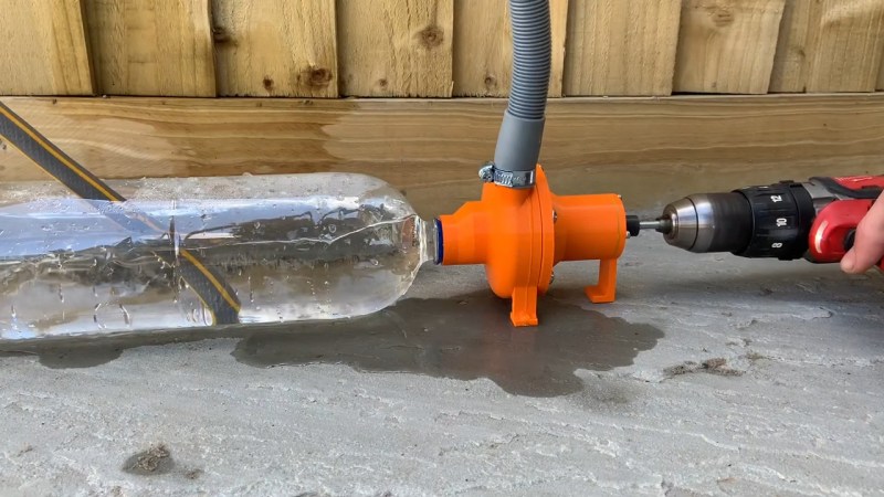
Once upon a time, 3D printing was about churning out tiny Yodas and Pikachus, but these days, useful things are regularly 3D printed too. A great example is this centrifugal water pump that can really deliver the juice, courtesy of [Connor].
The pump’s housings and impeller are all 3D printed in PLA, as well as the inlet which is designed for a 2L soda bottle to screw into. Gaskets are printed in pliable TPU to help seal the housings. There are a few ball bearings inside to allow the impeller to spin nicely, too, with hex head fasteners used to hold everything together and a long bolt used as the main impeller shaft. Notably, no shaft seal is included, so the pump does leak a bit, but it’s not a major concern assuming you’re just pumping water and don’t mind spilling a bit of excess. Turned with a drill at 1800 rpm, the pump is able to achieve a flow rate of 13 litres per minute, or a maximum head of 1.2 meters. The design is on Onshape, for the curious.
It’s a great example of how 3D printing can allow the creation of machines with complex geometry without the need for advanced machining skills. Instead, all the hard work is done on the CAD side of things. We’ve seen 3D printed pumps put to real work before, too, like this fertilizer dispenser. Video after the break.


It’s fun making stuff, but a self contained pump with magnetic coupling can be had for very little. So I salute this build and it’s orangeness :)
>without the need for advanced machining skills
Substitute advanced machining skills with advanced CAD skills – and deep pockets for the software, $1,500 per user, per year, in this case. Makes you want to see if there’s a more elegant solution that suits the home workshop better.
That money gets you about 136 harbor freight pumps with 600 lph.
Openscad + https://github.com/revarbat/BOSL2/wiki/bottlecaps.scad + hose adapter (looks easy) + some epoxy glue.
Openscad and easy in the same sentence. You sir, get extra points! ++
But he’s right.
OpenSCAD really is easy. Especially if you’ve never used it before.
Download (it’s free), install and run, New.
Type this in:
cube([10,10,100]);
Press F5, F6 and F7 in quick succession.
I did the above in 11 seconds. That is, created a 10x10x100mm rectangular rod from scratch, previewed, rendered and generated the STL ready for 3D printing.
Can you name any other CAD package where an absolute beginner can do the same model, from scratch to completion, in that time?
Did it in 8 in Fusion 360. OpenSCAD is very capable, but it’s incredibly difficult to model complex geometries without a lot of experience. And needing to re-render manually every single time you make a change makes experimenting with different sizes super time consuming. Recommending OpenSCAD to someone who’s never used any sort of CAD software is a great way to quickly deter them from ever trying to model stuff themselves.
That’s a very slanted argument, because it’s based on the assumptions that;
1. The “absolute beginner’ has learned 4 seperate commands, including the syntax required for one of them.
2. The end goal is a very, very simple shape.
OpenSCAD is a powerful niche tool, but easy to use it is not.
Of course it’s a simple shape, just as ‘Hello World’ is a simple program.
I gave full instructions to create and render that shape that a beginner can type. Or even, cut and paste.
My question stands – If you can describe in one paragraph or less how to get instant gratification of a similar 3D model ready for printing in any other CAD suite, modern or historic, expensive or free, in equal time, please tell me as I am genuinely interested.
Thank you R, 8 seconds is very commendable.
Now, as requested, please give your exact instructions how I, who has never used Fusion 360, can reproduce it. Every keystroke, every menu selection, every mouse move, every click and drag, to the same 10x10x100 dimensions.
Would appreciate you typing that up In a paragraph or less so I can give it a go – and have it work for me first time.
I would say time is a bit of a silly measurement of how well someone understands a software. How far is “an absolute beginner” going to get after that bit of instruction? I don’t know if you’d count it, but I’d say TinkerCad may be better for a beginner.
>I gave full instructions
That’s a silly argument. Repeating a “magic incantation” like that does not mean the user understands what they’re doing, or have learned anything about the use of the software. They learned exactly one special procedure. It’s like teaching the person how to fry a pancake, and then expecting them to understand how to whip up a cheesecake.
Ease of use means the software is obvious to the user, so they don’t NEED instructions or special knowledge to use it. What you’re confusing is efficiency for ease.
Huh. All this hate on Openscad. I’m a good cad operator and a bad programmer, but when I looked at the free options to support my 3d printer I settled on Openscad. I would think programmer types would find it super-attractive over learning cadthink. And you can’t beat the parametric aspect in design iteration.
Of course when it comes to designing parts, some people need to see what the part looks like to design it, while others decide in advance and in abstract, and the part comes out as it will. That has nothing to do with whether you’re used to programming. A lot of design is about “does this look right?” rather than knowing exactly where to put a hole or a feature. Seeing it defines where it needs to go.
If I were to use OpenSCAD, I would need a sketchpad next to the keyboard to draw the shape out first, plan how to structure it, then write the code accordingly – which can be hours of work to compensate for the lack of features in the program, and assumes you can draft by hand well enough.
All of them can do that. At some point it is easier to draw than code, and that is why complex surfacing would be very tough in OPENSCAD.
The question does not stand. It’s superfluous.
Being able to “race” to a .stl of a fixed dimension cube in 27 key strokes is as irrelevant to ease of use as how fast you can output hello world is to what programming language you should use.
I mean, if copy and pasting were something to actually argue over, wouldn’t the answer just be to hit a website and download a cube?
As soon as you want to execute a project, you need to learn the system you are executing it in. OpenSCAD has a lot of mental overhead.
OpenSCAD requires no more mental overhead than learning Python. Or BASIC.
And yes STL and other format shapes can be downloaded, but is it going to be the required size?
I’m not arguing that OpenSCAD is for everyone. Or that it can do complex renders as easily as conventional CAD drawing can – it can’t. Some things are downright near impossible in it.
But, alluding to the ‘Openscad and easy in the same sentence’ post above, it _is_ easy to get started and learn. If you’ve programmed in any computer language, you’ll have little trouble.
> than learning Python
In other words, it requires a heck of a lot. One does not merely “learn python”, truly that is, without also knowing a bunch of other concepts and stuff about programming and computers in general. Otherwise you “learn” it by simple repetition and memory.
Points accepted. You are right.
As long as you only add cubes and cylinders, do some subtraction with cubes and cylinders, everything is fine.
Doing roundings or chamfers is a nightmare. Adding stuff at positions that are somehow rotated and translate is a one-time-only-and-never-touch-again solution (like adding a strut/prop).
Lots of stuff is extrude. Works nice but OC is slow as hell and I tend to add cake to coffee then.
It just happens to work like a programmers brain. That’s why I like it.
Onshape does have a free hobby option that is free. Only catch is that all designs are public. I have used that for years and had no problems
“Advanced CAD skills”
Literally the only *maybe* difficult-to-model piece in this pump is the impeller, and that’s ONLY if you’re concerned with efficiency and don’t want the vanes to be a simple arc segment. This may come off as a little elitist, but, as far as I’m concerned, if you’re not at least competent in you modelling and intend to make practical parts, there’s little point in owning a 3D printer in the first place.
Even if you don’t want to…let’s say…”borrow” Inventor or Solidworks, there’s plenty of free or low-cost CAD options out there.
As an aside…”no shaft seal is included”. Why? An o-ring costs a few cents, at most, in even relatively small quantities. I know it probably doesn’t really matter here, but, come on. Why does it seem like almost every YouTube channel with a focus on making 3D-printed things isn’t actually any good at designing 3D-printed things?
Not like it takes any time to develop the skills required to understand fits, finishes, fasteners, assembly, and all those important things. 🙄
Way to nitpick a cool idea to stroke your own ego, I don’t see you putting your ideas on the line. Congrats on the uber important idea of an o-ring shaft seal, your ability to contribute will take you far.
Why aren’t armchair critics better at design?
That part wasn’t a jab at the guy making the pump. It was a jab at the OP implying that 3D printing is somehow comparable in expense and difficulty to machine work because you “need” to know CAD, as if modern machining and design work in general doesn’t benefit heavily from the same.
And, no, I’m not ego stroking by criticizing something. There IS something of an actual issue with a lot of these channels trying to print every single piece of something, and it’s obvious that, a lot of the time, it’s not for the challenge of doing so. I’ve seen assemblies with the friggin’ WASHERS 3D printed. I just feel like I see too many trying to make the printer be the end-all, be-all thing maker, when that’s a sub-par use of the technology. 3D printers see their best use when used in conjunction with other manufacturing technologies, parts, and materials, not when trying to replace them.
Also, for the record, I do something along the lines of commercial/industrial maintenance for a living. My design ability and repair work is on the line every day. Considering I still have a job, I’d say they’re holding up well enough.
I used to “borrow” SolidWorks but I stopped using it after I discovered that it turned my PC into FTP server distributing over 70 gigabytes of child pornography. I literally had to crush the SSD to be safe.
> there’s little point in owning a 3D printer in the first place.
The comparison made was between having traditional manufacturing tools and skills, vs. having a 3D printer and 3D modeling skills. The argument is you don’t need to be a skilled craftsperson – well now you need to be a skilled 3D modeller and pay a lot for the right, or deal with the inefficiencies and idiosyncrasies of low-rent CAD software.
Everything is easy once you already know it.
Your O-ring point is classic. If you don’t know what an O-ring is, you probably won’t even think to use it. Why buy an O-ring when I can print a TPU one that works worse?
An o-ring makes for a poor seal and extra friction. Use a silicone rubber cable gland instead, or a proper shaft seal.
You can get a Fusion 360 Makers license. It’s good for a year at a time.
OpenSCAD is free forever.
I’ve gotten decent at FreeCAD. It is also free, and you can do some pretty complex designs with it, but I’ve found it to be a bit buggy, and when you have a lot of elements in one sketch, performance can slow to a crawl. I messed with OpenSCAD a bit, after I had some experience with FreeCAD, and I just can’t see myself doing much with it. It’s a matter of personal taste, and, except for IntelliJ IDEA, I’m allergic to paying for software.
I use Fusion 360, free for hobbyists
Fusion 360 is not free. Discuss.
I needed something important made so I bought the commercial CAD software (solidworks, AutoCAD) and I hired mechanical engineers the use the programs. I’ve been able to do what they do faster and with better results using Blender.
Free software is the way to go. Not these BS semi-free but upgrade to blah blah blah, stay away from those packages unless you absolutely have to (for me it’s Odoo).
When I do wood CNC projects, I design the model in blender, then import into LibreCAD and trace with vectors instead of using blenders point-cloud. For 3D printers I go straight from blender to an stl that I send to the printer.
Why waste time with paid software that changes from the top-down with primary decision makers being non-technical CEO’s (or technical ones who went to the dark side). Let the decisions be made by evolving and forking git repo’s.
It sounds like your CAD needs and view of people not in your field is pretty basic to be honest. Ah, the little people. Yes, industry wants to be beholden to forked github versions of OPENSCAD. LOL. Some of us just want to get the part made, some people want to make everything a software programming exercise. If you are a carpenter and you have a hammer…..
Craig, I apologize for coming through that way. I don’t mean to take away from Engineers with a high level of understanding and who use expensive CAD software to do stress analysis. But even there I see from academic papers algorithms and methods in Blender doing high level analysis. But most are not making or pushing those decisions – they are plugged into a company with those already in place.
“Some of us just want the part made” Exactly my point. From personally experience, I am able to knock out a part much faster in blender vs solidworks or autocad even with people more experienced than me. This is anecdotal and hard to compare the skills of me v them, I really don’t have the time to do a large study on that; sometimes you just go with personal experience.
And when I get a new desktop/laptop or want to show someone my design, I just do a `sudo apt install blender -y`. One line. Done. Solidworks/AutoCAD you deal with licensing and all kinds of non-sense. I understand if you want to be *professional* then you must buy commercial software especially if that is what you do every day for a living. But while I enjoy 3d modelling, it it a relatively small part of my overall projects. And I do not have the time to get caught up unless it’s absolutely critical. For example, figuring out how to go from blender to model ready for CNC router to cut a 4’x 8′ sheet of MDF took some effort but saves so much time since I use the same program (blender) to create many different projects.
>knock out a part much faster
Define “part”.
Correct me if I’m wrong, but isn’t Blender models primarily polygon based? That is, you don’t really have smooth curves – except as approximations. Secondly, I can’t imagine the pain of defining things like threaded holes in Blender.
https://blender.stackexchange.com/questions/53293/is-blender-actually-useable-for-engineering
The consensus seems to be that Blender is pretty limited in terms of parametric design and constraints, which makes it fast and easy to build up and object but then difficult to change anything about it. Everything is a mesh, so curved objects don’t have well defined features because they’re made out of flat sections. Blender is basically “if it looks right, it is right”, even if some surfaces are clipping and objects are not perfectly solid.
In a CAD program, what you’re also looking for is some sort of history or hierarchy tree that defines the order of operations, such as revolving a cylinder on a lathe, then transferring this onto a mill and milling a flat on it, then drilling a hole, then tapping the hole. When the engineer makes the model, they should also be thinking about how to manufacture it, which flows naturally form the way the program works. If you try to do silly things like relating the location of a hole to a feature which you then remove, the solver will throw errors at you.
Blender’s workflow is generally destructive, so you end up with just the final part geometry once you’re done all the operations. It looks to be difficult to go back to the beginning and change something about the initial shape without re-doing the entire part. This is fine if you know exactly what you want, and bad if the customer comes in and says “No, I wanted six evenly placed holes, not five”.
Hey dude, you are correct: Blender gives you points (polygons) not vectors. This is why I import the stl from blender into a vector program like LibreCAD then trace the model. I could have built it from scratch in LibreCAD but this is much faster for me. Maybe one day I or someone else with create python plugin that does the work of tracing for us but I am very grateful to be able to go from a blender model into a vector file I can run on a CNC. And while I do threaded holes in Blender, I would have to figure out how to trace it in the vector software if I wanted threaded holes in something other than plastic.
For example, I designed a slot machine for a customer. The majority of the time was spent developmenting the software/firmware to operate the machine but those components need to go into a cabinet. So I made the model with blender mixing parts being sent to the CNC router and 3d printer. Printer parts go straight to the plastic printer, done. CNC router parts sent to LibreCAD, traced, then that file sent to CNC shop.
Yes, you are also correct in the blender work flow generally being destructive but it does not have to be.
For example if I want to make a cylindrical hole in part, I will create the cylinder. Then I add a Boolean modifier to the part and select the cylinder. Now if I hit apply, it destructively modifies the part making a hole. However if I simply do no click apply and just hide the cylinder from the view port then nothing is lost.
So in your example of a customer wanted six holes instead of five, that would be no factor. I often make changes like that.
This is were showing you a picture would do a lot of good. Maybe I’ll make a video on my process.
To make a simple example of how CAD software is more powerful than Blender, I once did a simple rectangular panel with holes around the perimeter.
It starts out by defining a sheet of metal, then on top of that I made another drawing that references the first geometry and defines a bunch of reference lines that split the part into a grid. This grid changes when its reference points change, so it always conforms to the size of the panel and the holes end up evenly spaced, no matter which size I specify for the underlying sheet. The same is true for the mechanical drawing, because when I change the model, the drawing automatically updates, so I can crank out the drawings for a new panel faster than I can print it out. If the customer wants a box “yee big”, no problem.
> I could have built it from scratch in LibreCAD
LibreCAD is a 2D program, not a 3D modeller. It’s a drafting tool that resembles the original AutoCAD. You would find it difficult and slow to draw up parts from scratch with it.
>Maybe one day I or someone else with create python plugin that does the work of tracing for us
Usually in a proper CAD software, you would just click on the part you already made and select “export face” to get a DXF/DWG or some other format file with the outlines for CNC, laser, water jet, etc.
So what you’re saying is, Blender is fast because it doesn’t require you to consider any of the groundwork for the later operations at the start, which you then do in a different program after the fact, but it’s still more efficient for you?
We thought we’d run this through CFD to see what it looked like – there’s some interesting flow at the outlet (the design could be better).
Feel free to check it out here!
https://www.simscale.com/workbench/?pid=5783003886710485879&rru=172d5b31-ec98-4fe5-8f2f-0b5a4a1bd875&ci=00db6aaa-fd93-47a0-adfa-9d9cc6983ddb&ct=SOLUTION_FIELD&mt=SIMULATION_RESULT
This is basically what we do everyday for replicating Centrifugal Pumps Parts. Things are getting a lot easier than they used to be. It took us nearly 20 years to offer a decent amount of replicating pump parts per https://accapumps.com/centrifugal-pump-parts/