[Lauri Pirttiaho] from the [Swiss Knife of Electronics] channel explains how to simplify your resistive divider keypad design on Hackaday.io.
The usual method involves building a resistive ladder that gives unique and equally spaced voltages for each keypress. If you have just four or five discrete buttons, it isn’t terribly difficult, but if you have a 12- or 16-keypad matrix, things get complicated. [Lauri] looked into the past to come up with a better way, specifically a 646 page, 1 kg textbook from 1990 — Analogue Ic Design: The Current-Mode Approach by Toumazou, Lidgey, and Haigh. He learned that sometimes what’s hard to do in the voltage domain is easy in the current domain.
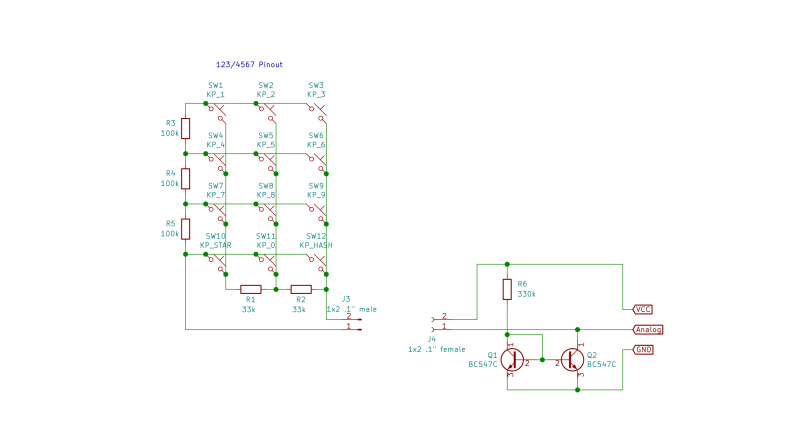
Normally you’d throw in some resistors to form different voltage dividers depending on which key is pressed, and read the resulting voltage off of a voltage divider with an ADC. But that means using the voltage divider equation, and the difference in voltage between keys can get very small. Dropping the voltage divider and measuring the current through a current mirror generates a linear voltage across its output load resistor that can be easily read by your microprocessor. And [Lauri] has posted an example of just such a program on his GitHub repository for an Arduino.
Heavy analog electronics, for sure, but something to keep in mind if you’re reading more than 12 keys. Do you have any examples of solving problems by looking into old and/or less-common techniques? Let us know in the comments below.


I’m actually interested in the flip side of this. Car steering wheel buttons tend to use this mechanism, is there a good way to interface to this with a microcontroller to generate the input to a voltage divider system?
I want to be able to have different buttons do different things based on mode, have a rotory encoder, etc so I can’t just attch resistors to buttons.
Use several outputs to drive a r/2r digital to analogue converter, pass the output to your voltage detection circuit
To be fair, all it needs to do is generate the correct voltage for a given key.
It is a fairly simple task, and to a degree, you can just measure the needed voltages with a multimeter and then just use a micro with a good enough DAC to do the job for you.
does anyone know if the steering heel buttons are really that trivial? The aftermarket head unit I have is programmable, (hit a button, then hit the function to assign to that button), so if it really is as trivial as a DAC, (or PWM + filter) that mkes life easy.
I was thinking in terms of digital pot
Some buttons use a CAN bus, but many are just analog voltages. I just did this on mine with an intermediary translator that takes the button voltages and converts it to the radio’s remote control protocol. Had to figure it out because my vehicle isn’t officially supported but I found the diagram in the car’s tech manuals and it had 2 groups of buttons with 2 output signals and and a common connection to ground. The manual had the voltage values for when it was connected to the stock stereo and it was literally 5V all open, 4V vol up, 3V vol down, 2V Mute, 1V Enter which presumably means it assumes the stereo itself has some known impedance that the buttons create a divider against.
Sometimes the buttons might be going to a LIN Bus microcontroller.
in my case I know it’s a resistor set
Maybe use the good old fashioned parallel port “sound card” resistor ladder concept.
To save on pins you could have a serial to parallel shift register with latched outputs and feed it to a Darlington array chip. You may be able to piggyback one on top of the other if the pinouts are favorable. No pcb required, just slip it inside some wide heat shrink and your done.
most new cars pipe said matrix into a converter and the radio gets commands via CAN…
in my case it’s a 2006 honda with a android auto 10 head unit
From a practical standpoint
Why does this method exist? With a few buttons maybe but with many use a matrix. I just trashed a 3 speed fan with a sweep mode. I assume that it used this stuff. The tiny tac switches nowadays are poor at making a perfect connection as it is. Fan=dust, tac switches get dirty. The 3 speed button fails, press hard. The fan frequently engaged the annoying sweep motor and starts moving when I changed the speed. A simple 4 position 3 speed mechanical switch will do, We can’t put a timer or remote on such touch button “smartness” marketing. I’ve seen TV’s do this.
If car wheel buttons us this, that’s madness. Can can. My ’99 cruse control gave out years ago. The same press to their death tiny tac buttons, built like a diamond anvil that is used to create the highest pressures man has made. We crush to death the contacts whatever they are made of, carbon or plated metal.
That current mirror eats up a fair amount of dynamic range at the bottom end, maybe up to a third (or more) of your available ADC range (depending on whether you take your ADC reference from the dirty rail or from a clean reference).
So, instead, use a JFET from the positive rail as a constant current source: one fewer transistor, and increased dynamic range & better noise immunity (or more buttons distinguishable).
What’s the purpose of Q1? With collector-base shorted it’s acting like a regular diode. 0.7v reference between base of Q2 and ground?
yes. that’s what it’s doing. it’s acting as a diode with the same I-V curve and temperature characteristic as the other transistor’s junction.
Exactly that. It biases the base of the other transistor to a point equal to the current that is going through Q1, assuming both transistors are identical.
There are several inexpensive Chinese amateur radio trancievers that use this method for remote control from the hand microphone to the CPU. I also ran into this many years ago in an intercom that was in our shop for repairs. I have also seen it many years ago in ademco brand alarm system remote keypads.
In the Netherlands (and no doubt in some areas of the USA, as most of our railway signalling from the ’50’s was based on GRS (General Railway Signalling) licenses) level crossings used this trick to signal this function. One wire connected all level crossings along a certain stretch of line, each with their own resistance. When a crossing malfunctioned, the resistance changed (I can’t find what exactly causes this) but the ohmmeter does no longer read one of the normal resistance values and a no-doubt analog electronic system apparently lit a red light in a control room when this happened.
I was about to ask how old is this method, are there any patents. 50s sounds too old, how did they sense the signal?
I bought a couple of 4×4 Robotdyn keypads ( https://robotdyn.com/button-keypad-4×4-module.html ). The have a resistive network, which allowed me to use them with the ADC port of a Digispark (attiny85) to make a macro keyboard. Cheapest macro keyboard you can make.
This is a typical restive divider keypad. With 10 resistors it produces a monotonic but not (ven closely) uniform set of voltage levels. The number of counts between levels at 10 bit ACD varies from 20 to 110.
At typical current levels of the application, less than 10 µA, the bottom is below 0.5 V with normal small signal transistors. With 3.3 V and 5 V rail this still gives plenty of ADC range for detecting reliably 3×4 keys: >18 counts with 8-bit ADC and 3.3V VDD.