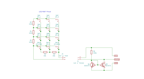
Improved Technique For Resistive Divider Keypads

[Lauri Pirttiaho] from the [Swiss Knife of Electronics] channel explains how to simplify your resistive divider keypad design on Hackaday.io.

The usual method involves building a resistive ladder that gives unique and equally spaced voltages for each keypress. If you have just four or five discrete buttons, it isn’t terribly difficult, but if you have a 12- or 16-keypad matrix, things get complicated. [Lauri] looked into the past to come up with a better way, specifically a 646 page, 1 kg textbook from 1990 — Analogue Ic Design: The Current-Mode Approach by Toumazou, Lidgey, and Haigh. He learned that sometimes what’s hard to do in the voltage domain is easy in the current domain.

Normally you’d throw in some resistors to form different voltage dividers depending on which key is pressed, and read the resulting voltage off of a voltage divider with an ADC. But that means using the voltage divider equation, and the difference in voltage between keys can get very small. Dropping the voltage divider and measuring the current through a current mirror generates a linear voltage across its output load resistor that can be easily read by your microprocessor. And [Lauri] has posted an example of just such a program on his GitHub repository for an Arduino.

Heavy analog electronics, for sure, but something to keep in mind if you’re reading more than 12 keys. Do you have any examples of solving problems by looking into old and/or less-common techniques? Let us know in the comments below.

Continue reading “Improved Technique For Resistive Divider Keypads”

Circuit VR: Current Mirrors

Last time we looked at Spice models of a current sink. We didn’t look at some of the problems involved with a simple sink, and for many practical applications, they are perfectly adequate. However, you’ll often see more devices used to improve the characteristics of the current sink or source. In particular, a common design is a current mirror which copies a current from one device to another. Usually, the device that sets the current is in a configuration that makes it very stable while the other device handles the load current.

For example, some transistor parameters vary based on the output voltage which causes small nonlinearities in the output. But if the setting transistor has a fixed voltage across it, that won’t be a problem. The only problem with mirror schemes is that the transistors involved all have to match in key characteristics. For that reason, mirrors are usually better on ICs where the transistors are all more or less the same. You can get discrete transistors that have multiple devices built on a single substrate, but these are not very common.

Continue reading “Circuit VR: Current Mirrors”