
There was a time when building electronics and building software were two distinct activities. These days, almost any significant electronic project will use a CPU somewhere, or — at least — could. Using a circuit simulator can get you part of the way and software simulators abound. But cosimulation — simulating both analog circuits and a running processor — is often only found in high-end simulation products. But I noticed the other day the feature quietly snuck into our favorite Web-based simulator, Falstad.
Back in March, the main project added work from [Mark McGarry] to support AVR8js written by [Uri Shaked]. The end result is you can have the circuit simulator on the left of the screen and a Web-based Arduino IDE on the right side. But how does it work beyond the simple demo? We wanted to find out.
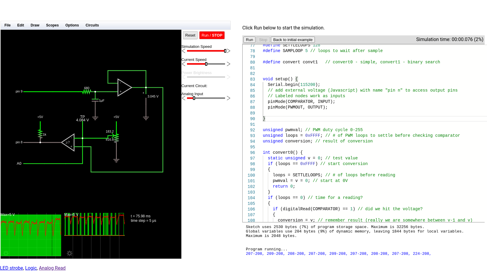
The screen looks promising. The familiar simulator is to the left and the Arduino IDE — sort of — is to the right. There’s serial output under the source code, but it doesn’t scroll very well, so if you output a lot of serial data, it is hard to read.
Nothing is Perfect
I love just about everything about the Falstad simulator and having an Arduino cosimulation is great. But there is one really important issue that may get resolved eventually. Normally when you draw a schematic you can save it as text or encoded in a link. If you click the link or import the text, everything is back to the way it was when you saved. I use that in a lot of Circuit VR posts so you can click on a circuit and see it live.
However, the simulator does not save the source code in the virtual Arduino. You have to do that yourself. That means if you have everything working, save your circuit, and close your browser you’ll have to recreate your Arduino code next time. Luckily, I tested this out before I lost any work. There should be a big red warning on the page, though.
What that means, though, is that I can’t give you a link to follow along with examples. Here’s what you can do:
- Have a look at the source code.
- Open the simulator.
- Copy the text from the top of the source code comments and paste it into the simulator (detailed instructions in the comments).
Just don’t forget to save your source code changes. If you make changes to the circuit, you’ll want to export them to text and copy them into the source code so you can save everything together.
An Example
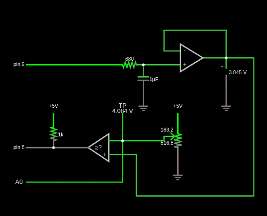
I wanted an easy example that showed the benefit of using cosimulation. I settled on looking at some alternatives for doing an analog to digital conversion using successive approximation. A virtual potentiometer provides an input voltage. There’s a comparator and a buffered PWM output. Here’s the schematic:
Input/Output
There are three interface points to the Arduino. The PWM output is set as an external voltage using the “Inputs and Sources” components (remember, the output from the Arduino is the input to the circuit). Conversely, the comparator output and the connection to the Arduino’s analog converter (A0) are labeled nodes from the “Output and Labels” menu. The names are significant, including the spaces.
The Code
In theory, the code is pretty simple. You guess a voltage and read the output of the comparator to see if you are right. There are two methods in the code and you can switch between them by setting the convert define to convert0 or convert1.
On every pass through the loop, the code calls one of the convert functions to manage the successive approximation process through a different algorithm. It also updates the PWM output on each pass.
The first approximation algorithm is very simple but not very efficient. It guesses each output voltage starting at 0 and moving up 1/255 V on each pass. When the comparator goes from false to true, you know the input voltage must be less than the current voltage but more than the previous voltage.
The second algorithm is smarter and works like a binary search. The first guess is 128/255. That voltage is either higher or lower than our target. If it is lower, we remember that the bit should be on and, either way, move to the next bit. In other words, the second test will be either 64/255 or 128/255 + Simulide64/255. Again, the new value is either high or low and will determine the state of the next bit.
The first algorithm could finish fast or it may have to count all the way to 255 to find the answer. The second algorithm always takes 8 measurements. There’s no way for the comparator to tell us our reference voltage is exactly equal to the input even if we could define what that means for an analog signal. So we have to measure each bit and decide if it should be on or off.
The output appears in the serial terminal. The first number is the result of the conversion and the second is the value from the built-in converter for the same voltage.
Voltage Reference
Generating the reference voltage is the key. It would be possible to use 8 output bits and an R2R network to generate an output voltage quickly, but that eats up a lot of pins. Instead, I used one pin to generate voltages using PWM. This isn’t as fast, of course, because you have to allow the RC filter time for the voltage to reach its desired value.
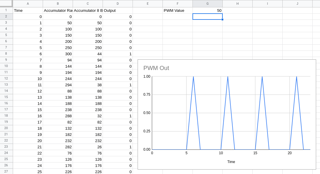
Pin 9 generates a PWM signal using a time-honored technique. Suppose you want to generate 20/255 (about 8% duty cycle). You take an 8-bit accumulator and add 20 to it repeatedly. The PWM output is the carry out of the top bit. You can find a spreadsheet with the logic, but you’ll have to imagine the output waves are squares since the spreadsheet helpfully draws straight lines between points.
To do this right, the code should run on a precise interrupt and equalize the time between outputs. However, for this quick demo, I’ve assumed the time for calling the main loop will be regular enough. I considered doing it on an interrupt, but — honestly — I’m not sure how faithful the simulator is, how time-accurate it is, and it doesn’t appear you can easily add libraries to it, so you’d almost certainly have to manage the interrupts at the register level.
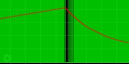
The output signal gets smoothed by an RC filter. The values here are interesting and it is fun to watch the scope as you vary the parameters in this part of the circuit. You want a noise-free reference signal. So that implies a big capacitor. However, a big capacitor takes more time to charge and discharge, so the voltage will take longer to settle. It is a classic trade-off. Do you want a noisy fast response or a clean slow response?
In this case, the pot probably doesn’t change very fast, but in real life, the input signal might be changing all the time and you might even consider a sample and hold on that input to make sure it doesn’t change while you are in the middle of guessing.
Tuning
Obviously, you can change the RC values easily in the simulator. It is even possible to add sliders to set the values graphically while the simulation is running (the pot is set up to do this already). Changing the code, however, requires a stop and restart.
In the code, you can change the number of loop cycles the convert routines wait to allow a new PWM value to settle (SETTLELOOPS) and how long to pause between readings (SAMPLOOP). The interactions between these numbers and the RC values are critical. Larger RC time constants require more time to produce correct results. Smaller RC numbers will require less time, but the noise will introduce errors. Take your pick.

The Verdict
This is a toy example. The PWM generation suffers from some issues and PWM isn’t a great idea for a conversion reference. Still, it shows a good bit of what is possible with the cosimulation available with Falstad. I am really looking forward to the next time I need some exotic signal fed into a circuit. Just using the Arduino as a function generator will have its uses.
I do wish you could add libraries and save an entire project more easily. Still, there are many what-if scenarios you could simulate quickly and easily using this tool. Since it has only been in the code base for a few months, I’m hopeful some of these issues will work out over time. Add debugging to the mix, and it would be a real winner.
Tinkercad allows you to simulate Arduino, but not with the circuit sophistication of Falstad. It does require an install, but we are always surprised we don’t hear more about Simulide.


Hi there !
Being a fellow Falstad user, I have some update for other users: we had the option to create subcircuits for a while, yet there’s also the possibility of using “external javascript” to toggle some pins either via custom js code .. or some avr8.js code ( like in the above article ).
I also quite recently heard about “wokwi”, which does offer few components to “virtually connect” to a simulated arduino ( somewhat close to what Tinkercad offers, or what 123dCircuits used to offer ), but simulating 2 uCs at the sale time / within same app seems not currently possible.
I was looking to debug a wip web UI by adding it to the mix using websockets & cie, for “advanced plotting” of some measurements from the Falstad circuit directly or through a simulated Arduino, but as the time was lacking, I ended up only testing said “subcircuits” & previewing code for an i2c connected oled using “wokwi”
Also, “last but not least”, I’m still looking for the best way to simulate some uC pins behavior in Falstad ( in other words, having a “symbol” for uC & some “exposed pins”‘, allowing usual plotting in virtual scopes on what’s happening (..).
Also quick reminder: Falstad hosts a lot of neat simulators aside from “circuitJS”, for example another tool to debug filters ( I wish I knew how tu best use both & also wonder if we can do some stuff LTSpice do directly in circuitsJS .. )
Anyway, kudos to the authors :)
While you are visiting all of the elec sim options in the FOSS world don’t forget QUCS (Quite Universal Circuit Simulator) release 0.0.9 includes a VHDL text editor which allows libraries of hand-crafted device models to be constructed. This raises the interesting question of if QUCS can then use VHDL generated by Digital (derived from logisim). I get a sense of a convergence happening in this area were the full path from bare metal physics up to program code running on emulated devices is possible.
more surprised that it’s taken this long for this to be done than that it exists, which I am glad for! arduino-circuit interaction can be critical and almost impossible (without already knowing about the other sims mentioned in other comments) to find a sim for, it’s something that’s not very Searchable