
Ask any electronics hobbyist or professional what the simplest building blocks of electronic circuits are, and they’ll undoubtedly say resistors, capacitors, and inductors. Ask a mechanically-inclined person the same question about their field and the answer will probably be less straightforward. Springs would make the list for sure, but then… hmm. Maybe gears? 80/20 aluminum extrusions?
As it turns out, there are a handful of fundamental building blocks in the mechanisms world, and they’re functionally very similar, and mathematically identical, to the Big Three found in electrical engineering.
Mechanical Equivalents
Before we look at the components themselves, let’s step back a moment and think about voltage and current. Voltage is a potential difference between two points in a circuit, sometimes called electromotive force (EMF). It turns out that EMF is an apt term for it, because it is roughly analogous to, well, force. Voltage describes how “hard” electrons are being “pushed” in a circuit. In much the same vein, current describes the rate of electric charge flow.
Now that we’ve got that squared away, let’s break down what each of the three popular passives actually does, starting with the humble resistor. Resistors convert voltage to current — that is, the 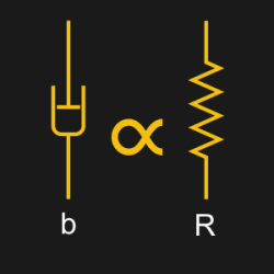 voltage potential across a resistor is proportional to the current flowing through it, and vice versa. To put it in terms we discussed above, the flow of electrons traveling through the element is proportional to the force that it exerts back onto the circuit. It resists the flow of electrons by pushing back harder when they flow faster.
There’s a mechanical element that behaves in exactly the same way — the dashpot or damper. A dashpot is often a fluid-filled cylinder with a piston the liquid can flow past, and it pushes back harder the faster it is compressed. Your car suspension has a damper and a spring on each wheel — as you go over bumps, the springs let the car bounce a bit, and the dampers keep it from bouncing forever. The faster the car bounces, the harder the dampers push back. If you didn’t have dampers to dissipate the extra energy, much in the same way resistors dissipate energy in a circuit, you would be in for a rough ride.
Next up is the capacitor. Capacitors store and release energy — a voltage across a capacitor causes it to accumulate charge, which causes the current to drop until the device is fully charged, and the current 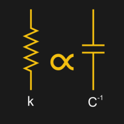 has fallen to zero. If the voltage across the element increases, the current will pick back up momentarily as the charge continues, and if the voltage across the element decreases, then the current will reverse, as the capacitor discharges until it reaches equilibrium with the applied voltage. The rate that voltage changes is proportional to the current passing through the device.
Again, let’s think about this mechanically. We have a device that stores energy and pushes back when force is applied, and then releases that energy when the force is removed: a spring! The speed at which a spring is compressed determines the rate at which it’s “push back” increases, until the “push back” is equal to the driving force — just like a charging capacitor. Your car’s shocks are a single-pole RC lowpass filter, but there’s one more element in the system to talk about.
Inductors are kind of the opposite of 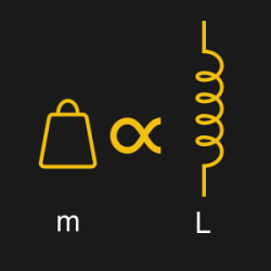 capacitors: in a capacitor, the rate of voltage change is proportional to the current, while in an inductor, the rate of current change is proportional to the voltage across the device. Additionally, capacitors store their energy in an electric field, while inductors store their energy in a magnetic field.
Differences aside, the two are quite similar, but inductors are bit more difficult to conceptually reconcile into a mechanical element. What device has an acceleration proportional to applied force? Everything! Everything with mass, that is. Good ‘ol 
It’s a cruel trick of fate that the physical spring, the analog of the capacitor, is drawn the same as the electrical resistor, the analog of the dashpot. Worse, the inductor looks more like a spring than either of them. Make sure you keep them straight.
Time For Some Differential Equations
Now that we have a conceptual understanding of how these elements are related, let’s take a deeper dive into the math behind the components to show that they really do behave identically. If you’re content with the mostly math-free discussion we’ve had so far, feel free to skip ahead to the example below. By convention, we’re going to think about velocity and acceleration as the first and second time derivative of position, 

Looping back to the resistor-dashpot relationship, let’s look at the equations that govern each. The resistor obeys the all-too-familiar relationship:

While the dashpot, relating force and velocity, operates as:

Comparing these formulae, it becomes clear that the resistance 

Taking a glance at the equations that describe the “motion” of capacitors and springs, we can note a similar resemblance. For a capacitor:

And for a spring:
These equations sure do look similar, and much the same as before we can see that the capacitance 


Ah, that’s better, and now the equation even accounts for the initial displacement 
One more to go! Here’s the differential equation that governs the behavior of an inductor:

And as you’ve come to expect, here’s a suspiciously-similar-looking equation for the motion of a mass:

Which is, of course, the old classic 

Example Time
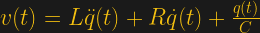
Now that we’ve defined a bunch of equations, let’s stick them all together in an example! The old classic here is a cart connected to a wall by a spring and a dashpot. We can even take that and model it as an electric circuit. Our example doesn’t show this, but its worth noting that springs in parallel and series behave just like capacitors in parallel and series, and the same goes for dashpots and resistors. Here are our two equivalent models of the system:
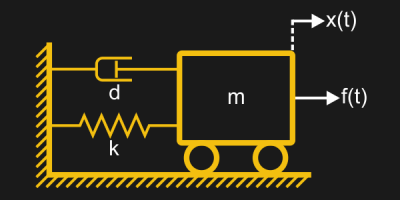
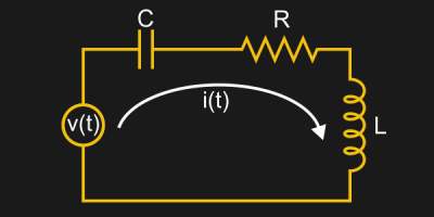
Time for some analysis. Much like the Kirchhoff Voltage Law says that the voltages in a closed loop must sum to zero, the forces in a closed system must also balance out. I’ll spare you all of the math, but the equations work out to:


Alright, these look a tad different, but remember when we talk about current, we’re really talking about the rate that charge 
Building Blocks
Let’s bring all this math into reality. Are masses, springs, and dampers the building blocks of mechanical engineering? Well everything has mass, so I guess we’ve got that one covered. As for the other two, it really depends.
Personally, I often use springs in my designs, and I’ve yet to use a dashpot anywhere that isn’t a controls problem set from back when I was in school. There are also many different kinds of mechanical engineering. Structural engineers, for example, have a very different idea of what “building blocks” are than what thermal engineers do. Thermal engineers use the idea of “equivalent resistance” in an entirely different way, to describe heat transfer.
For dynamics problems, the mass, spring, and damper are unarguably the core components but there are a ton of other interesting mechanisms and devices out there that are ubiquitous in other subfields of mechanical engineering and design that we can explore in future articles. For now, at least we know how to analyze simple electric circuits by building a mechanical system.


Physics is physics.
Hmmm… Physics is physics…
Amen! And a differential equation is a differential equation. Shades of Gertrude Stein!
The same equations show up in many different contexts. Fluid flow in porous media is the heat equation in different dress.
Masses, springs and dampers are most definitely *not* the building blocks of mechanical engineering. There are the rather important and *very* complex subjects of “mechanics of materials” and “statics and dynamics”. You can model the vibration of a bridge with masses, springs and dampers, but that will not tell you if it will fall down or not. Significantly more work required.
” For now, at least we know hot to analyze simple electric circuits by building a mechanical system.”
Darn there goes my gun targeting computer. ;-)
https://hackaday.com/2013/03/13/retrotechtacular-mechanical-targeting-computers/
“It resists the flow of electrons by pushing back harder when they flow faster.”
What does this statement even mean? The electrons in a DC circuit are barely moving.
Donnie, you’re out of your element.
i guess it means that resistors have some kind of arareness of rate of flow, pushing back and creating a negative feedback loop.
Dang, i thought resistors were passive devices.
Maybe they’re Swiss resistors?
Lowering the pressure and current with an orifice is a better analogy. And the pressure drop voltage drop. Turning some electromotive force into heat at a given current.
It the idea behind Bond Graph, it is a very fast way to write differential equations. It had been used in automatic transmissions. BG have lot of use.
https://en.wikipedia.org/wiki/Bond_graph
A very interesting program is 20 sim https://www.20sim.com/ the demo is free.
The major great point of 20 sim is you trace the BG ( or electrical, mechanical , hydraulic and thermal system and you get the simulation AND the differential equations great
Sadly I do not know open source program in this field.
Modelica is what you need. Modelica is the language to write the equations in; object-oriented and all…
OpenModelica is the open-source tool, used to do simulations (more polished ones exist commercially). Try it out, it is pretty easy and contains a lot of examples, including electrical circuits, mechanical, thermals, etc…
A mechanical 555 would be the start of a microcomputer. ;)
As a hobbyist I often try to describe the idea of hobby electronics as basically the same as Lego. The main difference is that the bumps on the blocks don’t always line up, so we use wires to connect them. Sometimes you need a little block sometimes a big, but you’re still building things by lining up the bumps.
This was done a while ago by McLaren.
They figured out the J-damper this way (Inerter) by filling out this map, and exploring the “missing” pieces.
Hello Christian,
the inerter has to be credited to Prof. Malcom Smith (Cambridge University). McLaren implemented his invention.
As people might have noticed, there is an incompleteness in the description on the mass/inertance in the above article:
all the circuit, respectively mechanical elements should work between 2 connection points, so the delta voltage is considered, as done with the spring in the middle of the article: f(t)=k(x(t)-x_0)
The description for the mass uses a ground based formulation, mechanically often called inertia. Whereas the Inductor can operate on a delta voltage. This is what Prof. Smith noticed and put into a mechanical device, the “inerter”, basically consisting of a gearbox and a flywheel, now acting upon the 2nd derivative of x_2(t)-x_1(t).
This gave the engineers the possibility to create higher order filters for the suspension. Most commonly an arrangement is used that allows a stable (aero)-platform and a “softening” at higher frequencies, placing the inerter in parallel to the spring.
Greetings
Georg
My masters supervisor used to teach (still likely does) bond graphs to mechanicals. What are bond graphs? They are a way of generically drawing all of these things. Electrical, mechanical, hydraulic, magnetic, etc. So what you say? Through visual inspection you can now do 2 things, figure out if it’s indeterminate (and easily fix it, like a “compliance” in a double pendulum mechanism) AND generate the system of linear of equations.
But all domains have equivalents so if you’re keen, you can easily interconnect multi-domains. So you can model electrical, mechanical and more TOGETHER!!! and generate one system of linear equations. My masters used this to shortcut this. High level controller gives force, you chase force with another PID controller. We skipped the cascaded controllers by modeling the electrical actuator into the mechanical domain with bond graphs and poof zero lag controller that gives voltage out and not current or force.
This analogy is even used in material modelling. See for example https://en.wikipedia.org/wiki/Kelvin%E2%80%93Voigt_material