Building Blocks: Relating Mechanical Elements To Electronic Components

Ask any electronics hobbyist or professional what the simplest building blocks of electronic circuits are, and they’ll undoubtedly say resistors, capacitors, and inductors. Ask a mechanically-inclined person the same question about their field and the answer will probably be less straightforward. Springs would make the list for sure, but then… hmm. Maybe gears? 80/20 aluminum extrusions?

As it turns out, there are a handful of fundamental building blocks in the mechanisms world, and they’re functionally very similar, and mathematically identical, to the Big Three found in electrical engineering.

Mechanical Equivalents

Before we look at the components themselves, let’s step back a moment and think about voltage and current. Voltage is a potential difference between two points in a circuit, sometimes called electromotive force (EMF). It turns out that EMF is an apt term for it, because it is roughly analogous to, well, force. Voltage describes how “hard” electrons are being “pushed” in a circuit. In much the same vein, current describes the rate of electric charge flow. Continue reading “Building Blocks: Relating Mechanical Elements To Electronic Components”

Memristors On A Chip Solve Partial Differential Equations

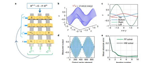
We were always taught that the fundamental passive components were resistors, capacitors, and inductors. But in 1971, [Leon Chua] introduced the idea of a memristor — a sort of resistor with memory. HP created one in 2008 and since then we haven’t really had the burning need to use one. In a recent Nature article, [Mohammed Zidan] and others discuss a 32 by 32 memristor array on a chip they call a memory processing unit. This analog computer on a chip is useful for certain kinds of operations that CPUs are historically not efficient at, including solving differential equations. Other applications include matrix operations used in things like machine learning and weather prediction. The paper is behind a paywall, although the usual places to find scholarly papers will probably have it soon.

There are several key ideas for using these analog elements for high-precision computing. First, the array is set up in a passive crossbar arrangement. In addition, the memristors are quantized so that different resistance values represent different numbers. For example, a memristor element that could have 16 different resistance values would allow it to operate as a base-16 digit.

Continue reading “Memristors On A Chip Solve Partial Differential Equations”

Beyond Control: Maths Of A Control System

Control systems are all around us, and understanding them is going to make you much better at hardware design. In the last article — Beyond Control: The Basics of Control Systems — we looked at an overview of what a control systems are in general with the example: “everything in between water and time is a control system”. We also observed control systems in nature, where I described my keen ability to fill a glass of water without catastrophic results. That discussion involved the basic concept of a block diagram (without maths) and we expanded that a bit to see what our satellite dish example would look like (still without maths).

I promised some big ugly maths in this article, and we’ll get to that in a bit, never you fear. First let’s have a look at how some basic elements: resistors, inductors, and capacitors are defined in the time domain. Don’t let these first few definitions turn you off. No matter how you feel about calculus, you don’t necessarily need to fully understand each equation. What’s more important is how the equations themselves combine to solve the circuit. Also important is that I will do everything possible to get out of doing difficult math. So stick with me through the article and you’ll learn that agony-saving trick for yourself!

A quick recap on transfer functions before we get going might be beneficial. A control system is used to define electromechanical behavior. For example: our satellite dish (from the previous article) at some point will need to be moved from one position to another position and as control engineers it is our job to determine just how this action will take place. I’m not talking about setting the mood for the big emotional robotic rotation, more like: not damaging the equipment or any people that might be nearby when moving the dish. For many reasons the dish would need to be moved with extreme care and in a very precise manner. The control system is the mathematical definition of that movement. Often the maths of the definition are nasty differential equations, (remember I’m avoiding any math that can be avoided, right?) so, instead of using differential equations to define the system, the transfer function will define the system with algebra, relating the output of the system to the input.

Continue reading “Beyond Control: Maths Of A Control System”