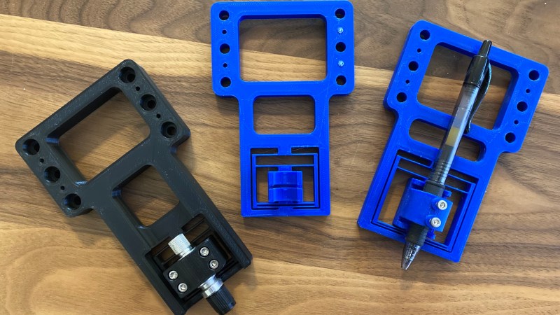
Game developer and eternal learner [David Tucker] just posted a project where he’s making linear flexures on a 3D printer. Tinkerer [Tucker] wanted something that would be rigid in five of the six degrees of freedom, but would provide linear motion along one axis. In this case, it is for a pen or knife on a CNC flatbed device. [David]’s design combines the properties of a 1-dimensional flexure and a spring to give a constant downward force. Not only is this an interesting build in and of itself, but he gives a good explanation and examples of more traditional flexible constructs. He also points out this site by MIT Precision Compliant Systems Lab engineer [Marcel Thomas] which provides a wealth of information on flexures.
[David]’s experiments showed that leaf-spring-like segments with a thickness of 0.4 mm provided the desired amount of force. We’re not sure how many iterations were required to arrive at this number — perhaps those mechanically inclined readers can offer up equations to predict the spring force ahead of time for a particular geometry. Even though printing springs of a precise force may be trial and error, at least 3D printers are good at making precise and repeatable thin-walled structures. Also note that since the spring force only needs to act in one direction, pushing into the paper or other working material, the spring design is asymmetric.
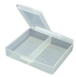
This approach is basically a living hinge of sorts, so there could be some longevity issues. On the other hand, yours truly has a small Tupperware pocket stamp container that’s well over 20 years old whose living hinge has yet to fail, so maybe they aren’t such a bad thing if done right. We wrote about 3D printing of living springs before. Our writeup last year on the Martian helicopter Ingenuity has a good picture of flexures, metal not plastic, which are integrated into its landing gear / legs. Do you have any project which have used flexures like this?


One of my favorite constant force compliant mechanisms:
https://www.thingiverse.com/thing:4624094
If you want to dive deep into compliant mechanisms checkout “The FACTs of Mechanical Design” youtube channel:
https://www.youtube.com/c/TheFACTsofMechanicalDesign
They have a really in depth series of lectures about designing compliant mechanisms:
https://www.youtube.com/watch?v=eE53W_Mc8j8
FWIW the flexures I’ve made also used 0.4mm thickness because that’s the nozzle diameter.
One of Dan Gelbart’s workshop series is devoted to designing flexures, which he cuts with a waterjet. One of the things he does is go through the procedure for designing flexure lever arms, which he chains together so a 5:1 lever is pushing another 5:1 lever and so forth until his fine adjustment screw is producing a nanometer-sized movement at the other end of the lever chain. I’ve tried printing those and they definitely lack the precision of the ones he’s cutting out of aluminum but the general design idea is obviously good.
Printed flexure springs using multiple spiral arms into a center, like an old fashioned large-to-small-hole vinyl record adapter, make for some great 1dof springs, quite stiff in all directions save for the translation axis of interest.
I have tried designing some similar flexures and found that certain axes weren’t as rigid as others. For example, in banner image, the third flexure has a pen in it. I would expect that the clicky button end of the pen would wobble up and down towards and away from the camera pretty easily.
Does this design have the same problem?
That sort of wobble will always exist to some extent – the flexure parts will twist some. But it should be reduced somewhat by making the flexure thicker in Z, and perhaps stiffening the x-y flex arms or adding more of them if the design specs allow. So perhaps try using something like spring steel flexy bits attached to the 3d print in this case – allowing you to define how stiff the spring needs to be easily, get a greater range of movement without deformation from a smaller flexure arm length as spring steel is a much better material choice for the role (in general).
But if you really need stiffness at the rear end of a pen holder like that really simply better off having another flexure holding the top of the pen too – making it very much harder to twist (beyond enough to accommodate the tolerances in production). The deviation a flexure can get through twisting should never be huge anyway, though it can look worse on the end of a long straight object, but holding both ends or at least nearer both ends will cut the amount of deviation possible to damn nearly zero.
One at each end. So simple and so brilliant! Thanks for the suggestion.
“This approach is basically a living hinge of sorts, so there could be some longevity issues.”
A well designed flexure does not stress the material till it yields. It stays well within the elastic realm of the material. Therefore it can be very long-lasting.
The hinges on my sons lunch box haven’t lasted 6months.
“A well designed flexure” clearly does not apply. Or more likely the criteria for “well designed” focused on low cost of manufacturing instead of longevity.
Depends, the wohler curve for many plastics is far more resilient than most metals (even nitinol alloys intended to flex at room temperature). As a side note, the material properties can change when dealing with single-crystal-growth metal billets (Ti turbine blades for example), and wafer scale MEMS devices. I will spare us the pedantic explanation reviewed in a tutorial I took, but essentially these mechanisms have almost no metallic grain boundaries in the alloy at that scale… so they tend not to initiate cracking which normally leads to a mechanism failing. This is why a DLP micro-mirror array can flip around at 20kHz for years without falling off in a few seconds… now DLP do still eventually fail… just not as fast as one would expect… ;-)
Remember we can each be partially right, and still miss the bigger picture:
https://en.wikipedia.org/wiki/Blind_men_and_an_elephant
Cheers,
J
Flexures are so cool. here is one i have been playing with. https://www.youtube.com/watch?v=XslPu3xliDAm
Awesome! Can you give more info?
The printed one seems ok, but I must say this metal one is really precision stuff
https://www.youtube.com/watch?v=CcTQoy_tBp4
Please can I have an EDM machine for Xmas!