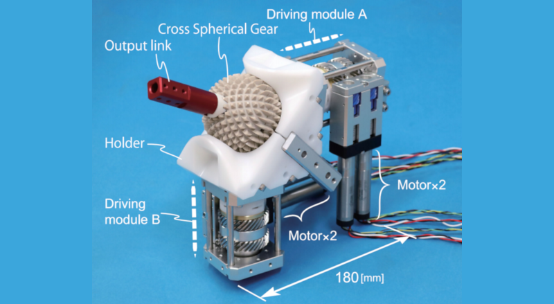
A common CAD operation is to take a 2D shape and extrude it into a 3D shape. But what happens if you take a gear and replicate it along a sphere and then rotate it and do it again? As you can see in the video below, you wind up with a porcupine-like ball that you can transfer power to at nearly any angle. There’s a paper describing this spherical gear as part of an active ball joint mechanism and even if you aren’t mechanically inclined, it is something to see.
The spherical gear — technically a cross spherical gear — is made from PEEK and doesn’t look like it would be that difficult to fabricate. There’s also a simpler version known as a monopole gear in the drive system that provides three degrees of freedom.
This looks like just the thing for your next robot arm project. The paper covers the kinematic equations you’d need, but doesn’t offer 3D printed models. However, it does mention that the parts were SLA printed, so it is possible to create the system with 3D printed gears.
With the recent trend to merge robot arms with 3D printers, this could be timely. The last time we saw balls used in a robot arm, it wasn’t quite for the same reason.


Medical hip replacement merit?
Last time I looked in my anatomy book, power to limbs wasn’t applied from inside joints.
power to limbs wasn’t applied from inside joints *yet*
https://www.youtube.com/watch?v=WyK7lX4sk0c
This had me laughing.
It looks like a spherical version of the left and right hand threaded screw that was featured here a few months ago.
That’s what’s itching my brain! Had the deja vu feeling but couldn’t place it.
The craftsmanship/engeneering on the actuator units is a work of art
Amazing. The big downsides being wear and weight probably.
and you can’t really put any rollers / bearings on any axle or anywhere else to take up forces applied to the joint/ball.
You can if they are threaded bearings.
Agreed its really amazing, so elegant in function.
Not sure I’d quite agree on wear though – with such large tooth areas always engaged, but shaped to be smooth bearing surfaces it could last really well – at least in some situations. Though any debris getting in would I think wreck it almost immediately, as its so dependant on being able to slide round the sphere gear profile any extra friction and burs being created will in short order jam it up or wear out the fancy tooth profiles too much (I think).
Maybe just put the whole thing in a rubber sock and fill it with grease.
There’s nothing to say this couldn’t be made out of metal.
Yeah, my first thought was something like a driveshaft boot, and filling it with the same type of grease
Magnetic..in a coil…
Seems like a less-capable and robust CV joint.
Not really, all a CV joint does is transfer rotation in one axis, this is steerable, moveable, very controllable joint, not just power transfer..
To be fair a CV joint doesn’t HAVE to be constrained to a single axis of rotation. That’s how they’re typically used but you could have a dual gimbal joint with the rotational axes orthogonally located about the center of the CV and move it across a solid arc.
But it IS constrained to a somewhat narrow angle of movement, past which wear and drag rise pretty quickly.
Is the pointing any different from an alt-az with a tube that can spin on its axis? Just curious. Like a tracking camera for a SpaceX launch with a camera that can rotate.
I find this a quite intriguing mechanism but there is one thing I do not understand.
As soon as you attach something to the ball, it can’t fully rotate anymore, and a much simpler mechanism would work better
Without attaching anything externally to the ball, it’s hard to find an application for this.
Not sure I’d agree – in some situations you are definitely right a simpler mechanism could do the job. But as this gives ball and socket joint kinematics – all movements in every axis around one point it will be very useful at times, and probably much more compact than the simpler approximations of that movement too.
Obviously its got to prove itself durable, repeatable, maintainable in the real world, but it doesn’t look impossible for it to pass those tests once you take it out of the early prototype lab setting.
You could put something in the ball, e.g. a camera, for a nice swivelling eyeball.
Which is normally solved with regular pan and tilt motors. And if the swivel axis meet in the middle (As they usually do) the movements will also be the same.
The biggest limitation of this is that it has an inherent huge amount of friction. First, you can’t put ball bearings in it, but the biggest contribution of the friction is that it is generated at the perimeter of the ball. Sliding bearings usually have a small diameter to reduce the arm at which the friction works. The teeth in the ball reduce the area for the sliding bearings, which again necessitates a bigger ball for a given load, which again increases losses by friction.
That “Differential Inner Worm Gear” with “inner pinion” is yet again an extra source of a lot of friction, and on top of that, the inner pinion is very small and may wear out quickly (although it would be relatively easy to make it out of hardened steel).
Maybe this could be used as the wrist joint of a 6-DOF articulated robot arm, but it would have to be virtually free of slop and a long life expectancy.
But I do like the mechanism and hope it finds an application where it fits well.
Truncate the teeth for a larger bearing surface. Run the drives through seals. Enclose it with a boot that has a rotary bearing and seal around the output link. There’s a robot hip or shoulder joint that needs no bulky actuators or cables etc connected along side the structural part of the limb.
A lighter robot limb adds up to faster motion and less energy use. But how much static and dynamic load could this design take when built all in metal and lubed with the kind of grease used in front drive vehicle CV joints?
Too many mechanism may affect the longividity of the spare parts.especially if overloaded.
If of any interest to anyone, I had a go at making 3D models of gears and documented, for modelling’s sake really.
– https://www.floatingintheclouds.com/active-ball-mechanism-joint/
– https://www.floatingintheclouds.com/monopole-gear/
The monopole gear was quite tricky (for me!) and kind of interesting.
Having now printed them out & I kind of get it, so super-motivated to continue & recreate joint in its entirety.
Impressive. Keep going! Maybe I’ll machine these things from metal on my CNC.
If you make 3 monopole gears, then you can statically/electrically fix 2 of them and have the third one move on the sphere. This way, it’s possible to have a pointer on the sphere actually reach any position, not like shown in the video above. Think of 3 moving legs displacing on the sphere with 2 used to transfer power on the sphere and the last one in “free run”.
I’ve been looking around for a model of the monopole gear for a few days now, because I just can’t seem to be able to make it myself. My skills with Fusion are not good – I’ve been using Sketchup for years, but Fusion is another beast entirely. Is there any possibility you would release these models?
Found your guide on your side, but I have no idea how to use Rhino3D.
Thanks
Hey. I stuck some 3d ‘for print’ stl models here:
https://github.com/aegis1980/threejs-abenics/tree/main/gear_models
The hole in the mpg accepts a technics lego axle.
In same git repo is my attempt to model the geometry maths, based on original paper. ie rotations you need on the two monopole gears to get a certain position on sphere.
https://aegis1980.github.io/threejs-abenics/
I have kind of given up on it – a challenge to anyone out there!
Figure that theres no point in trying to build whole unit unless get maths working.
Thanks man!
Hey Jon, very interested in your design. Are you the creator of this joint or at least have access to the 3D print instructions. They would come in very hand for my project but I do have just a few questions regarding their size
Haha. No – not my design. Well beyond me! I built gears following descriptions in original academic paper hackaday post referenced. And tried (but gave up on) the maths for controlling.
Here (https://floatingintheclouds.com/active-ball-mechanism-joint/) was my few posts trying to recreate.
Original designer’s paper here (https://ieeexplore.ieee.org/stamp/stamp.jsp?tp=&arnumber=9415699)
Jon, I cannot model this for the life of me in fusion 360 even after following your instructions to a T. Is there anyway you could maybe record a video of you modeling it in fusion 360 and I can venmo you for your time?
Hey,
Ooooold post.
From memory I ended up modelling the monopole gear using Rhino and Grasshopper – essentially machining it virtually. Then imported into fusion. Is that what you are a having a problem with?
Will stick Grasshopper file on github if not there already (and if I can find).
Looking down comments here, it is looks like someone pre-dated my effort anyway – maybe the original author of paper?
[https://www.thingiverse.com/thing:4891402]
ps I never got maths working in virtual model [https://floatingintheclouds.com/active-ball-joint-too-hard/]. Gear not much use without this.
Turn it so the ball points down. Put three in a triangle. Now you have a vehicle that can go in any direction at any time
I can’t believe no one’s compared it to a ball-mouse! Surely I’m not the only one who thought it’d be an awesome little robot if the ball in a mouse could be driven. (Then again, I guess that could be done BB-8-style. How come I didn’t see /that/ before?) But this takes it to a whole new level!
Exactly! Ppl can use active magnets and literally get the same mechanism. No hassles to manufacture and dealing with the w nightmare.
This is gosh-darn excllent – a long held mechanism dream come true.
I want this active ball joint mechanism full set
A 3d model for this actually exists:
https://www.thingiverse.com/thing:4891402