Over the years there have been many designs for pan-and-tilt camera mounts suitable for single board computer cameras. Often they mount small servos for the movement, but those in turn present problems when the device finds its way outdoors. [GOAT Industries] is here with a novel solution to this problem, instead of trying to cover up the servos on the mount itself, the whole thing is remotely controlled by linear actuators through Bowden cables.
Testing was performed using Mole-Grips instead of actuators, and revealed a few design quirks. There are hefty springs to provide tension, and since they work against 3D printed assemblies those in turn have to be reinforced. The layout of the Bowden cable run is also important, as it has a bearing on the amount of springinesss in the system. But it provides a versatile pan-and-tilt mount for a Pi camera mounted in an IP-rated box, which is the object of the exercise.
For anyone wishing to build one the files can be found in a GitHub repository, and there’s a video below showing the device in action. Meanwhile it’s by no means the first pan-and-tilt head we’ve seen here at Hackaday, however many others are by necessity much more substantial affairs.


Stupid design.
To me it is questionable me how long the thin pins and poles in this design will withstand the mechanical pressure in the long term.
They will shear off, break off soon.
Both the support of the camera and the “liniar actuators” will be on strain if the camera is not in the default position most of the time.
Perhaps a better way would be to have a “neutral buyouncy”, so there will be no tensions in the mecanism in any position and the actuators role will be only to change the position, not to mentain it.
Only if you use incredibly overrated springs. There’s no reason to – there only needs to be enough return force to overcome the friction in the system.
You are correct about
questionable me how long the thin pins and poles in this design will withstand the mechanical pressure, which is why the pins are re-enforced with a steel insert.Video details (transcription of voice): That is the default position for the tilt, so it points quite far down, which is quite useful. During the design of this system, I did have problems with this pin, as you might expect. If you put a massive spring like that, it’s quite a lot of force on the pin. I did some calculations and it looked like it was going to break the pin with a massive spring like this.
What I did when I ordered this last set of 3D prints from PCBWay was get multiple versions of this disc with holes put into the middle of the pin. I didn’t think that the 3D printer would manage to do that—it was very close to the tolerances of the specification for the printer—but it’s actually done really well. I was able to slide a 2 mm piece of spring steel rod into that hole, and the spring steel goes all the way up to the top of the pin, reinforcing it. I was able to put this together without the pin breaking, which is basically what happened before.
Brake cables can pull and push. What are the springs for?
I think you might be thinking of a ‘control cable’, not a Bowden cable. Control cables are great for push and pull, but have much less flexibility than Bowdens, which is essential in this design. Bowden cables themselves perform very poorly in push mode with the inner cable buckling and even kinking up.
Well, it depends on the load. I don’t think there’s any distinction between “control cables” and Bowden cables.
The (lack of) flex cable management is yelling “compliant rolling-contact joint” at me. That’d at least lodge the FFC inside sheath that is constrained to a conservative bending radius.
And if that’s not your cup of tea and sealing hassle, round cables are the best match for split-grommet-type glands, and one can squeeze 2-lane MIPI into a short USB-C cable (+/- need for re-timer like SN65DPHY440).
or just something like https://www.innodisk.com/en/news/mipi-over-type-c-camera-solution
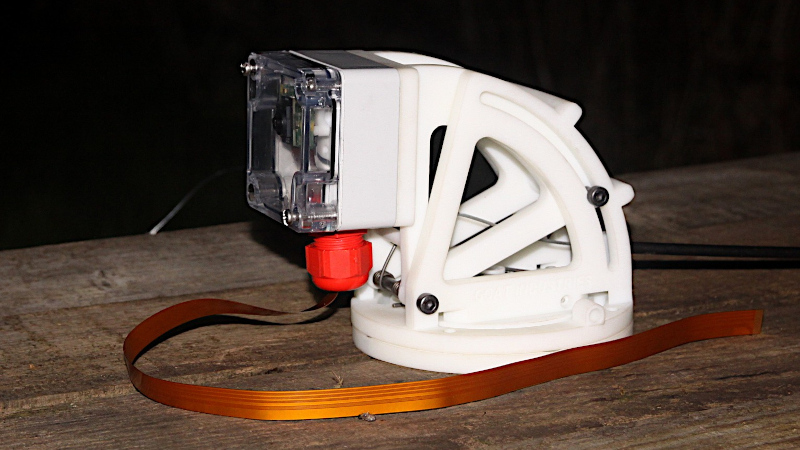
Exert from video transcript: ‘This is the camera section itself. It’s basically this box, which is IP rated. There is a ribbon coming out of this fitting here. To make it waterproof, you could fill that gland with resin and it would be 100% waterproof. The ribbon is a little bit flimsy; it’s not really going to survive well in an industrial situation, so it might need a sheath put over it to protect it.’
The design is simple, low cost and adecuate for the role, it is not going to outer space or the ocean bottom…
Well done and thanks for sharing!
Best regards,
Daniel F. Larrosa
Montevideo – Uruguay