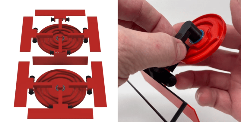
Seven-segment displays have been around for a long time, and there is a seemingly endless number of ways to build them. The latest of is a mechanical seven-segment from a master of 3D printed mechanisms, [gzumwalt], and can use a single motor to cycle through all ten possible numbers.
The trick lies in a synchronized pair of rotating discs, one for the top four segments and another for the bottom three segments. Each disc has a series of concentric cam slots to drive followers that flip the red segments in and out of view. The display can cycle through all ten states in a single rotation of the discs, so the cam paths are divided in 36° increments. [gzumwalt] has shown us a completed physical version, but judging by CAD design and working prototype of a single segment, we are pretty confident it will. While it’s not shown in the design, we suspect it will be driven by a stepper motors and synchronized with a belt or intermediate gear.
Another 3D printed mechanical display we’ve seen recently is a DIY flip dot, array, which uses the same electromagnet system as the commercial versions. [gzumwalt] has a gift for designing fascinating mechanical automatons around a single motor, including an edge avoiding robot and a magnetic fridge crawler.


It’d be nice if the red segment pivoting into place caused a black panel to move out of the way, and the red segment pivoting away allowed the black panel to move back and close the gap.
Just encase it so that the inside is pitch-black. If you fear stuff/dust entering the insides, just add a cover plate.
This would keep the mechanical complexity at bay…
Pretty nice mechanism. Do you mind explaining or sharing a reference on how I can design this kind of mechanism? Suppose I want to change the sequence of numbers or characters. How do I do to make this wheel? And also thanks for sharing this.
If you search for “Da Vinci’s Drawing Machine” you can find some elaborate examples using these sorts of notched cam mechanism.
Here is a link to my black out video: https://youtu.be/MKMwE1yvrSA.
Greg
Exactly: https://youtu.be/MKMwE1yvrSA
With almost the same mechanism, it’s possible. Instead of having the segments swing inwards, you can essentially have them slide with the circular pattern pulling the segments sideways. The segment plates will then be a black/red piece.
The cams would have to be much wider in that case.
Or turn two colored round drums and leave even less of an gap for dust to enter.
Maybe put clear pins on the inside of the segments to push spring loaded black covers aside when the segments pop up.
Make one side of the segments dark. Put the rotation axis through the middle, like a flip dot. To keep the stroke length of the sliding arm, have a crank a convenient radius. To avoid the dead point, make the segment a prism.
https://i.imgur.com/WgAObnd.png
You can save one part if you allow the arm to bob up and down a bit.
You can also make the segment mechanically bistable (with a cam or a magnet) and make the arm flick it.
The rotation or FlipDot approach sounds good. I think this would need less force than to move the whole segment up and down.
Yes, the rotational moment of inertia is minimal when the axis passes through the center of mass, and there’s less air resistance too.
The retaining cam / magnet would increase the force required to flip the segment for the benefit of not having the segment wobble as the cam turns.
One could easily replace the segment with a two-colored roll/cylinder that stays in place without changing the design too much.
That is absolutely beautiful.
In an age dominated by microprocessors/software, it is deeply satisfying to see mechanical devices like this.
That complex behavior can emerge from a simple mechanism is noteworthy, but what I find most impressive is the shear elegance of the design.
Thank you very much!
Clever. Clever things brighten my day :-) I look forward to a clock!
Genius! Those should be available commercially in multiple sizes. Perfect for daylight readability and rather low power.
We count from 0 to F today!
I thought we only counted from 0 to 1.
> all ten possible numbers.
AbCdEF are numbers that are possible on a 7 segment display. There’s more than ten possible numbers.
Also, don’t forget H, etc.
I am wondering how tricky a sixteen segment version would be. Seems like it might be better to push upwards and or sideways, making the cam have a variable depth too.
Back in the 80’s I had a nightstand clock that used a similar cam system. The cam disks were perpendicular to the display surface. This allowed a simple means of driving a gear train from the side, with reduction as the “message” was passed from one digit to the next.
Each transition made its own quiet but distinguishable noise. As a result, I didn’t need to set the alarm feature. My brain was listening to the sounds, and I could wake up at any desired time.
Remarkable! Sir, thanks for this.
Tolerances being what they are, I wonder if the mechanism will always achieve a full “shutting” of the flap so as to display the segment as “illuminated”. Perhaps having some compliance in the actuator arm and a bit more lift in the cam lobe would be in order.
Some great comments here. There are a couple more mechanical 7-segment display designs mentioned on this site. Use the search function and take a look around.
Patet Vocem: LEDs > Easier, Better, Cheaper.
At this size, minimal power.