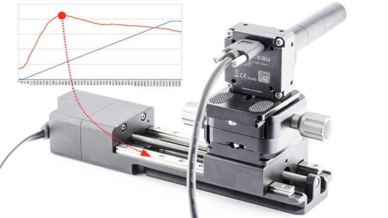
Here’s an interesting experiment that attempts to measure the quality of a linear rail by using a form of visual odometry, accomplished by mounting a camera on the rail and analyzing the video with open-source software usually used to stabilize shaky video footage. No linear rail is perfect, and it should be possible to measure the degree of imperfection by recording video footage while the camera moves down the length of the rail, and analyzing the result. Imperfections in the rail should cause the video to sway a proportional amount, which would allow one to characterize the rail’s quality.
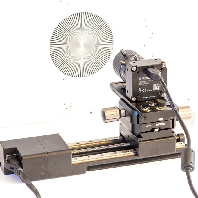 To test this idea, [Saulius] attached a high-definition camera to a linear rail, pointed the camera towards a high-contrast textured pattern (making the resulting video easier to analyze), and recorded video while moving the camera across the rail at a fixed speed. The resulting video gets fed into the Deshaker plugin for VirtualDub, of which the important part is the
 deshaker.log file, which contains X, Y, rotate, and zoom correction values required to stabilize the video. [Saulius] used these values to create a graph characterizing the linear rail’s quality.
It’s a clever proof of concept, especially in how it uses no special tools and leverages a video stabilizing algorithm in an unusual way. However, the results aren’t exactly easy to turn into concrete, real-world measurements. Turning image results into micrometers is a matter of counting pixels, and for this task video stabilizing is an imperfect tool, since the algorithm prioritizes visual results instead of absolute measurements. Still, it’s an interesting experiment, and perfectly capable of measuring rail quality in a relative sense. Can’t help but be a bit curious about how it would profile something like these cardboard CNC modules.


This may be one of the best parts of hacking, identifying slight imperfections to narrow the gap to total perfection
This is an interesting approach. Simple and elegant.
Though, I do wonder how much of the vibrations comes from the lead screw.
One could argue that the lead screw only applies axial forces. But then it is a perfect leadscrew that also doesn’t sag under its own weight, nor have a bend in it either.
One doesn’t have to be a metrology expert to know that lead screws nor ball screws, or even belts aren’t perfect. They all will apply forces in all maner of directions. And the ball/lead screws can apply a lot if they have just a slight bend in them along their length, after all, a few µm here and a few µm there does add up.
But to clarify, I don’t say that the method is bad. I am just curious to how much the screw is screwing one over and skewing the results unfavorably.
A very good point, though if you attach the camera to the assembly as you intend to use it all of that is part of the charecteriseation anyway – doesn’t really matter which part is causing the warp/shake etc its happening in that spot with those combination of parts – you also didn’t account for what you attached the rail too – that can apply significant warp to the rail if you crank it down and its wonky…
Might still get some extra variation if the final assembly is able to pull any meaningful G or move relative to gravity, which would mean I suppose running the test a few times under different force directions if that really really matters. But in practical terms if the rail isn’t complete garbage just characterising it and the drive mechanism together aught to be sufficient.
Seems to me the best way to do this is in reverse though – shine a laser at a wall (perhaps with a projector screen with the deviation measurements printed on it) from the rail. Still very cool, and I’d love to see a few tests of other forms of linear travel – those ball bearing ones are getting cheap, and definitely the best for some things, but simple ground rod and bushings are another great alternative for many things, and I expect would be way more consistent, active air bearings could be interesting too.
Maybe there are better software for that, like DICE (Digital Image Correlation Engine)
Would a mouse sensor be a better tool for measuring deviation?
You can do really quite good tracking optically: look at some of the tutorials on YouTube on how to use the motion tracking features of Blender. It’s really quite remarkable that this kind of functionality is in fairly easy to use end-user open source software, and not just in software toolkits for building other things.
What a clever way of doing this. Nothing like measuring the quality of something with the tool is associated with, really smart! Didn’t realize that VirtualDub had such a plugin. You could do the same thing with Blender, which I’ve been playing around with recently, but since it’s probably more powerful and flexible, it’s probably harder.
Given the abundance of really sensitive low cost accelerometers it seems like this is a solution looking for a problem. I would think simply mounting a commodity 3-axis accelerometer on the sled would give far more accurate and useful information than a derived result from video stabilization software.
Can you detect sub-micron deflections with a low-cost commodity accelerometer?
Integration error from acceleration would be larger than from velocity, which is what visual odometry does.
Are the camera and lens accurate enough for the measurement of 0.5 pixels error to be meaningful?
There’s a slight misrepresentation here. This doesn’t measure the quality of the linear rail – it measures the quality of the linear rail assembly as a whole. Linear rails are wet noodles until assembled to something stiff, the design of which is paramount to establishing accuracy.
Assemble a quality rail to a ground steel surface and it will be flat in one dimension. Provide a ground shoulder and means of pushing the designated reference edge of the rail against said shoulder, and it will be flat in two. Only then are you able to attain the precision provided by the rail and carriage specifications.
Assemble that rail to a non-ground lump of anodized aluminium and it will only be as flat as the aluminium. Then when the temperature changes the assembly will bend like the bimetallic strip of an old thermostat because of the significant difference in coefficients of thermal expansion. High precision high preload components are often a waste of money in such designs, and when two rails are assembled, can cause binding issues due to resulting non-parallelism.
For transportation mechanisms and hobby-grade CNC such designs using zero or low preload components might be fine. For precision CNC or metrology though ground reference surfaces are a must. It is possible to use aluminium, but costly. Grinding aluminium is a challenge – its softness and low melting point require special considerations, as does the resulting aluminium dust. Also the design needs to account for thermal effects. Kern makes extremely precise CNC machines using aluminium by pumping coolant through it to keep the block at a consistent temperature. Check NYCCNC’s tour video.
You can get kits to make a stabilized HeNe laser to make an interferometer and there is open source receiver interfaces and you can get more accurate and probably more useful information. Like ID says above, the rails are totally dependent on what they are mounted on.
Huh. I wouldn’t actually need a measurement in distance, only a relative graph between potential options.
Seems like this might work a treat to characterize cheap linear solutions (against one another) in ultra-budget CNC. Especially if you were setting up a bunch of rigs for throughput.
Well done!
I wonder if you could have achieved the same or better resolution using a standard mouse and a lens.
The optical flow processing chip in a mouse can already do some really accurate surface tracking and the lens might let it get even finer resolution (within reason, And hopefully avoiding weird optical effects).