Tech companies like Google and Microsoft have been working on augmented reality (AR) wearables that can superimpose images over your field of view, blurring the line between the real and virtual. Unfortunately for those looking to experiment with this technology, the devices released so far have been prohibitively expensive.
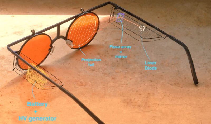
While they might not be able to compete with the latest Microsoft HoloLens, these laser AR classes from [Joel] promise to be far cheaper and much more approachable for hackers. By bouncing a low-power laser off of a piezo-actuated mirror, the hope is that the glasses will be able to project simple vector graphics onto a piece of reflective film usually used for aftermarket automotive heads-up displays (HUDs).
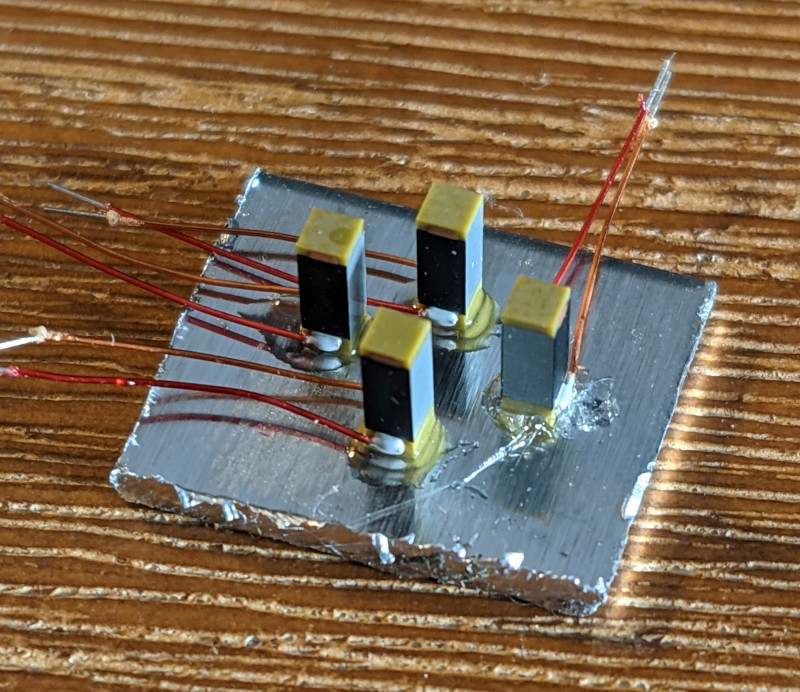
[Joel] has put together a prototype of what the mirror system might look like, but says driving the high-voltage piezo actuators poses some unique challenges. The tentative plan is to generate the vector data with a smartphone application, send it to an ESP32 microcontroller within the glasses, and then push the resulting analog signals through a 100 V DC-DC boost converter to get the mirror moving.
We’ve seen the ESP32 drive a laser galvanometer to play a game of Asteroids, but recreating such a setup in a small enough package to fit onto a pair of glasses would certainly be an impressive accomplishment. Early tests look promising, but clearly [Joel] has quite a bit of work ahead of him. As a finalist for the Rethink Displays challenge of the 2021 Hackaday Prize, we’re looking forward to seeing the project develop over the coming months.


Any noise to deal with?
I don’t see how the optics work out for this. To see something in focus from a particular part of your field of view, you need a bunch of nearly-parallel light rays entering your pupil from the appropriate angle, which is the same angle traced out by a ray going in the opposite direction from your pupil to that part of the FOV. The “nearly parallel” part is important, since that’s what makes that point of light look like it’s coming from far away. A point of light that’s about an inch away from your pupil makes a very diverging set of rays that you cannot focus upon.
Even if you had the properly-designed reflector that would redirect the laser beam from the moving mirror to your pupil, it would have the problem of requiring perfect alignment with your pupil. If you shift it just a fraction of an inch, the image will disappear (because the beams won’t enter your pupil).
If you could expand the beam to be very wide, and yet still be able to redirect it as a wide column of parallel rays that shine on your eyeball from various directions, you’d be able to solve both problems. Remember it’s the direction of the rays that determines the dot’s apparent location, not the location where it enters the pupil.
You mentioned that for focusing on really far away things (called infinite focus) the dot’s apparent location is determined by the incoming direction of rays entering your pupil. You also mentioned that a light source close to your eye will have a diverging set of rays, so if you try to focus on the horizon, the light will be smeared across your field of vision instead of appearing as a dot.
But what makes this work is that it is not an LED, but a laser. It doesn’t transmit light into a broad cone, and is more correctly approximated by imagining it as a single ray path. Moving the mirror alters the incoming direction of this ray, moving the dot.
That’s my understanding of commercial versions of this device
But the mirror is just the first part of redirecting the beam. How does this translate into the beam entering your pupil from different directions?
This image demonstrates the principle by showing the different ray paths:
https://ebrary.net/htm/img/23/1022/181.png
The reflector shown in this image (ellipsoidal) is not the same shape as the one shown in the HaD project (flat?) which is confusing. I don’t think this project will work as-is. But if he changes the geometry, it’s possible!
There’s much left out of that pretty crayon sketch. As drawn, it is useless and won’t work very well at all. The eye box (range of pupil locations and its size) is not zero, as implied there: the output rays must fill a box at least a centimeter in side at the pupil location to be remotely useful. The ray size (diameter) is also never zero, and does not encounter either mirror at a zero-size point. On the contrary, it *must* be millimeter-scale to work at all, which implies that when it hits that curved reflector, it will bounce off a family of rays going off in a range of angles.
The Fujitsu-bred heritage of that company implies they are not idiots, so I have to assume they are deliberately dumbing it down for the powerpoint version, or obfuscating it for competitive reasons.
Interestingly, Focals by North addressed all these issues, and explained it clearly on their website, before Google bought them and buried it. Bosch still mentions enough of it in their version that they clearly understand the issues though.
I’ve worked with a company that produced a display like this. In order to be usable, the laser needed to go through a “beam expander” first before being bounced off from a not-so-tiny moving mirror. Even so, the final eye box was still small, and the FOV was small as well. Trying to increase either would run into physical difficulties and other compromises. The company suggested that solving those problems would require an altogether different approach.
Because the light source was so parallel and focused in the first place the effect of its reflection will not be as diverging as you suggest, it should remain pretty focused, so the perceived depth of the spot won’t be as short as you suggest, it should be far enough away to focus on comfortably, perhaps feeling shorter than ideal for a hud but definitely should remain useable (at least assuming a focused small enough laser dot in the first place).
I also don’t see a problem with loosing the image if you look away – its a hud centred on your head not your eye position, so you won’t loose sight of it for long if your eyes track away, and when you track back it is right there, where it should be – I imagine it will be a bit like a rear-view mirror you glance to the right spot repeatedly…
Otherwise you are correct the optics on this are currently very flawed, but for a very limited FOV hud it should be perfectly adequate – if all you want is that compass/clock in the top corner of your vision the fact there is no curvature to the semi mirrored bit to allow the laser to be mapped to more of the retina (for that eye position and laser – mirror – semi-mirror angle) won’t matter.
The main question is what is happening when the beam hits the reflective surface? If the surface is acting as a mirror, then most of the time the beam is simply hitting your face and not entering your pupil. If the surface is acting as a diffuse scatterer, then you no longer have a set of parallel rays. If the surface is somehow reflecting the beam into your pupil, then you do have the problem of your pupil having to be in the right place, or else the beam will miss it. Even just looking left or right without turning your head can move your pupil many millimeters to either side.
But it doesn’t matter if you look away and loose the display – you know where it is to look back at when you want it. Your eye will always be in the ‘right’ place when you are looking for the HUD’s data.
A focused beam hitting a perfect mirror just reflects, the real word near perfect surface mirror they intend to use will add a tiny amount of scattering, but not enough to really matter, and the semi reflective surface on the glasses is a less ideal mirror so will probably produce some more significant scattering, but it still probably won’t matter enough..
As a glasses wearer, I know that my glasses are always moving around my face, and I frequently have to push them back up my nose. What this means for this display is that the “right” place is always moving around as well. Maybe that will be okay for some uses; for others, it may be aggravating. In any case, this still requires having the correct shape reflector, not an arbitrary one.
Even a “correct shape” reflector is not sufficient. It is impossible to produce an image from a point source (like a laser), via a reflector into an eyeball like that — even if said light source is scanned by bouncing off a mirror. It’s basic optics.
You can make approximations and get a blurry, small field of view image over a small eye box, but it’s pretty limited.
With a holographic element in the place of that reflector you can do much better: the holographic element simulates an optical element much further away. You still have to do tricks like replicating the scanned point source many times (via another holographic element) to appear like a large light emitting surface, to yield either a large field of view, a large eyebox, or some happy medium of the two.
The custom holographic element is also (obviously) wavelength-specific, so must be used with lasers.
At some point you need to decide whether a LCOS, OLED or DLP solution and conventional optics (e.g. google glass, Moverio, etc.) or waveguides (hololens, etc.) is just better.
There is no prototype of this and no progress on the project homepage. I call it vaporware. Just glueing 4 piezos with a (oh, horror) not-front-surface mirror, and putting two illustrations how this would be supposed to work is enough for this website to win a contest + get featured ? it seems the summer low tide of articles is already washing ashore
Like other people have said, this idea doesn’t work in principle. He’s creating an image a centimeter from your eye where you have no hope of focusing in on it
The idea isn’t that unsound – because its a laser the image on the ‘glasses’ isn’t fanning out the way putting a phone screen up to your eye that close would be – its a very singular beam back for each ‘pixel’ so the image is actually processed as something more like coming from the horizon, and the eye won’t actually be focusing the semi-reflective bit at all – In theory you can even paint images on the retina in focus no matter what the eyes lens is doing, as the eyes focal length will at most apply some slight scaling factor to the effectively pre-focused light…
Clearly this is only in the barely started napkin sketch phase, but the core concept isn’t actually unsound, just far from trivial to pull off.
” because its[sic] a laser”… There’s nothing magical about a laser as a light source here. It “fans out” just like any other light source.
“using the semi-reflective bit at all – In theory you can even paint images on the retina in focus no matter what the eyes lens is doing, ” Uh, no… The eye lens is still in the optical path, and it still acts like a lens, no matter what the source of the light — it can only form sharp images on the retina if the incoming light rays are parallel (or slightly divergent) to begin with.
There is a special case where if the exit pupil of the imaging system is tiny: Whether it’s a HUD, laser-based or CRT, or just a pair of binoculars: if the bundle of light rays is very small (say, less than a millimeter), then it acts like a small input aperture (F/22 in the case of a millimeter diameter ray entering the eyeball), with corresponding large depth of field. However, this means the eye cannot move, or its pupil will move away from the light ray — so you can’t see more than a very, very small field of view. If you have ever used a cheap high-magnification monocular, like 10×20, you’ll be familiar with the effect of hunting for the tiny exit pupil, even if you didn’t recognize it.
yes a laser does fan out, but its a marginal effect by design (for a good laser you can project a very small dot over vast distances) – so particularly over short distances its close enough to consider it a beam over a cone.
And yes with the lens of the eye in the path of a beam it can do something – but under the right conditions (mostly just knowing where the damn pupil is so you can target it) you can paint the retina with a laser – because you are putting through a single narrow beam for each ‘pixel’ the lens doesn’t do any focusing, and infact it can’t as there is not a meaningful divergence to focus, all it can do is shift, scale and perhaps distort how the image will land on the retina. Because each ‘pixel’ of the laser image is just a tiny beam of light it passes through the lens no matter the current lens shape and remains basically a tiny beam of light – so if the image comes in relatively directly into pupil distortion by the lens will be near zero no matter the focal length, but even if the eye is off axis this highly focused beam will remain a highly focused beam and just get a more significant deflection – its still a pretty focused spot of light on the retina, and all its mates that make up the image also remain so, though it will probably end up badly distorted and can definitely get its scale altered its still an ‘infocus’ image as far as the eye is concerned – as the nature of the laser creates sharp focused points of light on the retina, so you would see it clearly.
You have significant misconceptions of what a lens does and does not do. The diameter of the incoming beam, or whether the light happens to come from a laser, does not determine where it lands on the retina, nor whether it undergoes focussing or “shift, scale and perhaps distort” or not.
And, with a fixed reflector and fixed source location, how can you move the output beam (the exit pupil of the optical system, to use the correct term) to follow a moving pupil? (hint: you can’t)
It is not that “the nature of the laser creates sharp focused points of light on the retina” — it is the properties of the optical system that does that focussing. The laser is a convenient source of bright light, that is all. There is nothing magical about lasers here.
The ‘magical’ thing a moving laser dot can do is create an infocus image because the dot size is small enough and all the light is effectively parallel that through the lens of the eye it remains small a very small dot no matter the focus of the eye – enough to only activate a very precise focused spot on the retina. You literally are dragging a tiny tiny dot over the surface of the retina that creates very precise focused lines. It matters not at all what the eye’s focusing system is trying to do when it has effectively no divergence in the light to deal with all the lens in the eye can do is shift the landing spot for that beam path, not meaningfully change its focus, the beam is just too parallel and narrow for that- and by the nature of being a curved optical element coming in at odd angles changes the beam deflection more meaningfully than coming in on axis.
I also never said you could follow a moving a pupil – infact I’ve said it would have to be a fixed spot you look at to see! Its possible in theory to follow the moving pupil, or at least provide a much larger virtual screen for the laser to be bounced off so the pupil can actively scan to more information, its just not at all what this doodle is set up for as it stands (infact with the current layout on the doodle the beam path looks like it would draw only on the side of your nose)).
I’m also not saying its a great idea, personally I think the google glass or project northstar style for AR/Hud type stuff makes most sense more often than not, as the drawing on the retina type concept will only ever be visible when your looking right at it, at least without lots of extra optics, its clearly got limits.
I’m simply saying the idea itself isn’t flawed, it can work within some narrow confines, and with the right design it should actually be useable, maybe even ideal for what you want it for.
It is true that with a sufficiently small diameter pupil (the exit pupil of the optical system, defined by the diameter of the light bundle) the optical system will have a large depth of field, but it is clear you continue to have significant misconceptions of what a lens does here. For example, your comment “It matters not at all what the eye’s focusing system is trying to do when it has effectively no divergence in the light to deal with” makes no physical sense.
My point is that such a tight laser entering a lens is barely effected by it, when the dot area of the laser is small enough you can effectively say its point size isn’t effected – as within the sensitivity of the eye you are shooting it into it is not. The tiny point of light remains a tiny point of light – so the eye sees it as a tiny point of light (or moved fast enough an in focus line). The Eye’s focusing system isn’t able to make a meaningful difference in this situation, as the lens is both too close to the retina, so what effect is has doesn’t have enough throw to create a big change, and the retina not sensitive enough to pick up what difference was made.
Under those conditions all that really changes is where the laser can be deflected to – if it enters the pupil very straight, basically it can’t be, but at an angle where the change in curvature of the lens with focal length actually makes very big difference the image can become distorted, or moved around on the retina – because the change of lens curvature your moving laser covers is now significant rather than bugger all as it would be for entering the eye very straight.
Honestly, I commend your tenacity.
But, please, do yourself a favour and study some optical design methods before saying any more.
Having a laser reflected into your eyes via a mirror-like apparatus is just a small step away from looking directly at the laser. While I commend the ingenuity of the idea, this looks to me like an eyesight degeneration device (no pun intended).
As long as the power of the laser is low enough (and the amount of light entering your eye is also low enough) then the device is optically safe. A few HUD glasses already work this way.
But I checked the project page today, and under “components” it lists one 0.5W laser. Way more than enough to be a blinding device, lol.
Hopefully, moving the decimal and choosing parts carefully will allow this to be a safe, exciting build!
It’s all marketing, first you put glasses on voluntarily and then you have too. Maybe an LED would be a better light source?
LED don’t have the tight focus needed for this style of projection, it needs to be a laser, just a nice weak one.
It’s not the “tight focus” (whatever that’s supposed to mean here), it’s the brightness i.e. luminous intensity, lumens per steradian. An ordinary LED would work *exactly* the same, but would be much dimmer.
An ordinary LED really wouldn’t work at all, it would light up the entire mirror and everything else pretty much evenly, and by the time the light got to the next surface it wouldn’t matter what angle the mirror was at, the diffuse nature of the LED light would mean no meaningfully change in intensity remains – every angle of the mirror across its tiny movement would shift a massive fuzzy edged projected rectangle a probably imperceptible amount over the tiny ranges you would still be able to see that very rapidly dimming rectangle. Even looking directly at the mirror you just won’t really see a tiny point source, it will be a larger diffused spot..
Where the highly focused beam from a laser can be reflected at multiple times across many angles and still be a highly focused beam.
Again, these comments display significant misconceptions of what an optical system does, and ascribe magical qualities to a laser.
The only reason a semiconductor laser appears to have a narrow beam is because it is collimated to do so: remove the lens off a laser pointer and see the broad beam it produces without its output optics. To forestall the rebuttal: the physically long gain cavity of gas or solid-state lasers naturally perform the collimation function, so don’t need the output optics the semiconductor laser’s super-short cavity uses.
You can do *exactly* the same thing with an LED source, but because an LED is millions of times less bright on its effective emitting surface (its etendue, specifically), you literally never see an LED beam so narrow: it’s too dim. You can certainly produce just as narrow a beam with an LED source as you can with a laser, but it will be millions of times dimmer.
I’m not ascribing any bloody magic to a laser – the very nature of a good laser, even in diode form is that the only emitted light is in a very tight beam. Yes there are really good, and less good versions, but the core fucking concept doesn’t change…
Adding optics to do the same to an LED would just turn it into a bloody laser, at least done with any attempt at efficiency at all, some lasers are LED driven, but its not just a bloody LED then!
An LED described as you did would be taken to mean a single point source radiating light over some vast cone – as that is what LED’s do in their own right. Add the optics to make it behave like a laser and you wouldn’t describe the light source as an LED any more – its a blooody laser of whatever variety you built, driven by that LED – that would be like saying in every laser experiment ever its not a laser, its whatever particular method is at step 1 of creating that laser, that is what we call the light source, so a CFL, Fillament Bulb, etc – which is completely meaningless.
It is also important to note that most cheap laser modules do not really have much output power regulation. Diode laser power levels will vary a lot by temperature.
Looking directly into a class 1 laser is safe as long as you don’t use magnifying optics.
Lest anyone think this gives you permission at your next party to stare down the barrel of a laser pointer: NO, a Class I laser is NOT unconditionally safe.
The power density of even just a Class I laser, focused on your retina by your eyeball, can be about the same intensity as the surface of the sun albeit over a only a few dozen square microns.
The likelihood of damage is low because saccades will limit exposure time, but it still isn’t a terribly wise thing to do.
Your eye’s lens is a magnifying optic.
The piezo actuators that I know of have a displacement of a 1-2 micrometers per millimeter of nominal length. Looking at the construction of this, it would tilt your mirror by a small fraction of a degree.
Quick math assuming 4mm mirror raised on one side by 5um gives me something around 0.07 deg mirror deflection. With a very generous beam travel distance of, say, 100mm, you end up moving the point by +/-0.125mm, giving you an effective screen size of 0.25mm in one direction.
You could amplify this effect on a much longer optical path or with very precise and costly optics, but… no.
Am I missing something?
Now this point I agree with, I was wondering the same thing. I’ve been contemplating using piezo actuators for fine positional control for this very reason, they move very predictably a very tiny amount.. Though you have to start getting into virtual focus point to decide if that is useful – as with the highly focused beam the light appears to have come from very much further away than it actually has, and projecting that small screen out however far it ends up seeming to be from is going to be a bigger screen… Probably useable large, but as soon as you start moving into perceived size I start feeling the need to test it over just doodle some diagrams, as the workings of the adaptive eye and brain are even more complex than normal camera lens and those nice flat sensors/films, and those can be complex enough to figure out…
Kind of tangential, but where does a mere mortal (in Germany in my case) get their hands on piezo actuators?
I would be interested in a linear version of those “walking” piezo motors used in camera lenses, but when I searched there were no “hackerfriendly” options available.
Any recommendations?
The walking ones come in a few flavours I’m aware of, but actually getting fully assembled mechanisms around the piezo’s I’ve not seen available, ever. Have found every time I’ve looked sources for linear stacks wrapped in insulator you could make your own inchworm arrangements with (same sort used here by the looks of things), pricey enough to get into to put me off, so far…
I suspect they are not just available in hacker friendly forms because the travel is so tiny the mechanisms to get a walking stack (via any of the methods) needs to be rather precise and bespoke – its just not an easy off the shelf part for multiple use cases…
There used to be the SQL-RV-1.8 squiggle motors from Newscale Technologies, but I am not sure if they sell them directly anymore. If you are looking for a laser beam steering device that is really fast, look into 2-axis MEMS mirrors from Mirrorcle or similar company.
OK… let’s give this another try, this time hopefully with a reply to fho…
Linear, “walking” type motors are produced and sold by PiezoMotor (creative name I know…):
https://piezomotor.com/linear-motors/
is there any combination of “dots” in the near field that would appear as a focused “dot” in the far field? like a Moiré pattern or some such thing.
In general, no. Though you can conjure a special case with collimated optics and a suitable mask, or with a purpose-made holographic element.
Good luck to [Joel], but I don’t think it’ll be nearly as simple or inexpensive as he thinks. As he notes, it’s not a new idea and many people and companies have tried/are trying this approach with very, very few devices on the market to show for it.
For a start, only 3 piezo actuators are necessary. That’s a 25% cost saving and wiring simplification right there.
2 degrees of freedom (alt-az). Why would even three actuators be required?
Hi fho
Linear, “walking” type motors are produced and sold by PiezoMotor (creative name I know…):
https://piezomotor.com/linear-motors/
A former comment of mine was summarily deleted, no doubt for the ungracious way in which I pointed out the shortcomings of the editorial process.
But in that comment I also pointed out that the method described here CANNOT work, and a quick ray-tracing diagram will make it obvious why.
A few people here get that, but most comments here (and the project itself) clearly have not bothered to make the most simple sketch of the ray paths involved.
This is clearly inspired at least indirectly by existing technologies, broadly waveguide-types (Hololens, Lumus, others) or holographic (Focals by North, Bosch’s BML, Eyful). But this cargo-cult approach doesn’t understand the basic optics involved, and missing those fundamentals dooms the approach.
I’m sure the process of understanding WHY this can’t work will be a valuable learning experience.
I definitely learned from your comments, thank you for responding to mine! It hadn’t even occured to me that any width in the laser beam will result in it “fanning out” when being reflected from a rounded surface, but it seems obvious after you pointed it out.
Do you think a semi-transparent HUD in the form factor of glasses will be doable by hobbyists anytime soon?
Never say never…
Hobbyists have been making holographic optical elements for more than a half century.
It’s not even that difficult to make a numerically-generated one. I made a simple numerically-generated holographic focussing lens (a zone plate) in 1985 with an Apple ][, dot-matrix printer and a Pentax Spotmatic loaded with Tech Pan film. The only trick was to use a monochromatic low pressure sodium light to avoid chromatic aberration and eke that last required bit of resolution out of the stock 50 mm lens.
That stunt from 1985 isn’t sufficient to make a hologram of the quality needed for eyeglass-format HUDs, but far better methods exist now — a hologram printer was even featured in these HaD pages not that long ago.
It would be neat to conjure a way make the hologram in-situ though: using the actual source that will be used in the actual image generation. That way you’ll be sure to get the geometry and wavelength correct.
BTW: The Focals by North approach was a *very* promising entry to this field, and just as I was ready to plonk down my kilobuck on a pair, Google bought the company a year ago and… *crickets*. They suddenly went essentially dark, and all the technical content was removed from their web pages.
Makes you wonder what’s going on behind the curtain.
Why would this not flicker? There is no persistence to the larer as it is scanned. Unless it paints the frame more than 400x/second I would think that some people would be bothered by flicker.