When it comes to designing enclosures which aren’t simple boxes or other basic shapes, the design process tends to get somewhat tedious and involved as the number of measurements to be transferred into the CAD program begins to skyrocket. One possible shortcut here is detailed by [Sebastian Sokolowski], who describes a process that combines modelling clay with photogrammetry.
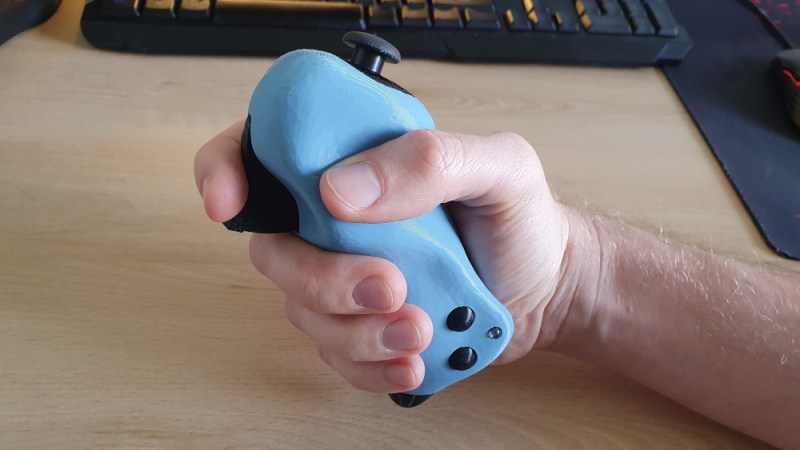
[Sebastian] covers the design of a hand-held controller that should fit ergonomically when grasped. This starts off with the electronics and mechanical components that have to fit inside the controller: inside a CAD tool (demonstrated in Fusion 360), these components are arranged with a simple box enclosure around them. This box is then 3D printed and with modelling clay the desired shape of the controller is created around this box.
With a modelling clay version of the controller ready, it is photographed from as many angles as possible before these photos are processed by the open source Meshroom tool into a 3D model. After fixing up some issues in the mesh and knocking down the vertex count on this model so that the CAD tool doesn’t suffer a seizure importing it, it’s ready for final processing.
Within the CAD tool all that is left now is to refine the imported model to refine its outer shape and to create the inner details for mounting the electronics, switches and other components.


Just brilliant! Organic shapes are such a challenge in CAD… I think you may have discovered a New Normal.
A NURBy solution.
one of the problems ive had designing controllers in cad was getting the scale right. i ultimately stole proportions from a ps2 controller, but then when it came off the printer the design was too small, and simply scaling it up was not an option because all the pcb mounting points would be off.
this is a much better way, though i have had mixed results with photogrammetry. make your surface too homogenous and the software will have a hard time picking out surface features to match up. also if you are using a modeling putty that is too shiny you will also have problems. dusting the final model with powder or colored chalk, or a splattering of a matte spray paint might give you a better scan. you dont want a too homogenous surface and want more of a chaotic patterning to get a better scan result. soft lighting also helps.
“You need a rough idea of what you want it to look like.”. Like this gallery quality fully shades drawing of the controller… 🤯
its just a rough sketch…
Is it possible use Meshroom photogrametry fully offline or is it same crappy cloud based SW like discontinued 123D from Autodesk?
Meshroom is fully open source and standalone
However it REQUIRES a CUDA-capable GPU – no OpenCL support
MeshROOM luckily isn’t Autodesk software. MeshMIXER is and was acquired by Autodesk and not updated since 2018. It does work without being online and requires no registration whatsoever. I guess they bought it/them for the code/know-how and now let it die. It is super capable as-is anyway!
I re-tried a scan that failed miserably a few weeks back following the tips from the video above and holy cow: awesome!
Get your photos right, add the camera sensor information and you’re 90% there.
It would be interesting to do a final pass with a hand coated in transferable ink. Then you’d have parts of the mesh that touch the hand highlighted and parts which can be altered without affecting the ergos marked separately
Really cool approach and the video covered all of the topics that normally come up with photogrammetry scanning.
Especially love the final 3d printed controller.
This looks really useful, thanks for sharing.
If you are going to do this a lot, you can probably consider mixing some colorful grains into the clay, so you don’t have to scribble on it with marker all the time.
it is also possible to use structured light. i’ve tried to use that laser thingy with difraction gratings creating starry sky effect (had to stop motor so it does not move the dots and dial the power all the way down to reduce reflections). Scan was not perfect, but certainly better than without it.