Introduced back in June, the IKEA VINDRIKTNING is a $12 USD sensor that uses colored LEDs to indicate the relative air quality in your home depending on how many particles it sucks up. Looking to improve on this simplistic interface, [Sören Beye] tacked an ESP8266 to the board so it can broadcast sensor readings out over MQTT.
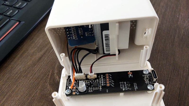
While some of us would have been tempted to gut the VINDRIKTNING and attach its particle sensor directly to the ESP8266, the approach [Sören] has used is actually quite elegant. Rather than replacing IKEA’s electronics, the microcontroller is simply listening in on the UART communications between the sensor and the original controller. This not only preserves the stock functionality of the VINDRIKTNING, but simplifies the code as the ESP doesn’t need to do nearly as much.
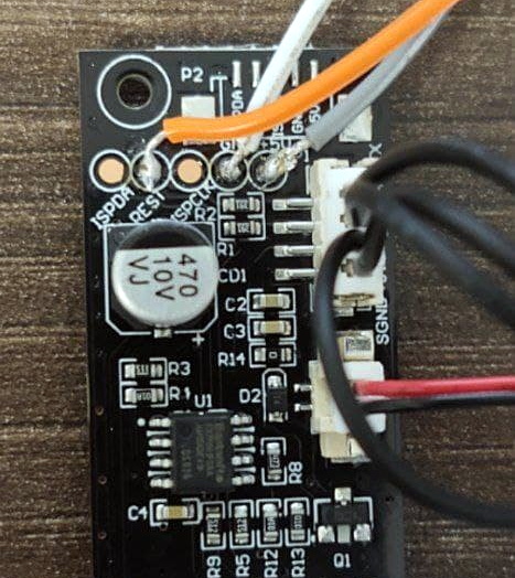
All you need to do if you want to perform this modification is solder a couple wires to convenient test pads on the VINDRIKTNING board, then flash the firmware (or write your own version), and you’re good to go. There’s plenty of room inside the case for the ESP8266, though you may want to tape it down so it doesn’t impact air flow.
While not required, [Sören] also recommends making a small modification to the VINDRIKTNING which makes it a bit quieter. Apparently the 5 V fan inside the sensor is occasionally revved up by the original controller, rather than kept at a continuous level that you can mentally tune out. But by attaching the sensor’s fan to the ESP8266’s 3.3 V pin, it will run continuously at a lower speed.
We’ve seen custom firmware for IKEA products before, but this approach, which keeps the device’s functionality intact regardless of what’s been flashed to the secondary microcontroller, is particularly appealing for those of us who can’t seem to keep the gremlins out of our code.
[Thanks to nexgensri for the tip.]


The fan speed change is part of the sensor’s cleaning cycle. Disabling it is going to eventually cause the it to fail, or at least provide inaccurate readings as dust builds up inside.
How about 3.3v and 5v to fan and diode preventing 5v to 3.3v output and maybe even diode prevent 3.3 to 5v output
I’d argue this isn’t the case, as the actual sensor used does not have have a fan – this is something ikea added to ensure airflow was drawn into the housing
From the sounds of the newer vindstryka, which is much quiter, I would guess IKEA did the same hack too. If I ever feel like , I might measure it too :p
To be honest, I would build the luftdaten sensor (https://sensor.community/en/). Not only does it include Temperture and pressure, the information is uploaded to the cloud and can be used to measure community air quality plus provides historical data
Just the sensor module in that one is more expensive than this whole thing. Add a bme280 and you can upload all the data anywhere you want.
Cost is not everything. Not only can you tap into an existing community led cloud infrastructure, you can also provide valuable data for the detection and tackling of air pollution
Which you can easily do by adding an ESP8266 to this sensor, as this project does.
“the information is uploaded to the cloud”
Lost me there.
>VINDRIKTNING
I wonder if that means “do not fart” in Swedish. :-)
In Dutch it would translate to Windrichting: the direction of the wind.
Google Translate, Swedish: VINDRIKTNING > WIND DIRECTION. Try it, and while you are there press the button to hear the Swedish word in use – bizarre!
https://translate.google.com/?hl=en&sl=sv&tl=en&text=VINDRIKTNING&op=translate
It only sounds that bizarre because when you use capital letters, Google Translate will spell out the word letter by letter instead of just reading it. Try writing it as vindriktning and it sounds much more human. 😉
Personally I would go with the lufdaten sensor. Not only does it add temp and pressure, but you can become part of the citizen science project to measure air pollution world wide, so your historical data can be easily accessed
The SMARTCITIZEN.ME has multiple sensors and costs less than complete and ready to go. Your noise sensors costs as much as SC1 that has noise, light, CO2, PM1, PM2.5, PM10, volatiles, and expands even more.
That is Your choice, but that is not what the article is about.
The article is about a simple but powerful mod to a cheap and readily available air sensor, that will enable data logging, remote monitoring, cloud integration and much more.
Duplicate post
Is that common particle sensor knowledge or a guess?
What exactly is ment by “cleaning cycle”? How does less airflow lead to it failing?
I do get the dust buildup _in theory_ however I’d assume that this would also affect other similar sensors such as ones measuring CO2.
I haven’t seen any effects on the ones I use since multiple years. Granted, as there is no fan and no forced airflow, there’s certainly less dust that could ever get in contact with it but does it really make that much of a difference?
Please elaborate further. Preferrably including some kind of source.
A ppm sensor works diff than a mox type sensor. The ppm sensor takes in particulates that can settle, cranking up the airflow can help knock this loose, but its job is to measure these particles and particles can settle. As for a source idk, read it on some technical manual while making an air quality sensor using ppm and mox sensors. Talking about how frequently to run a burn cycle or cleaning cycle depending on various sensors and the accuracy changes over time.
Yep. I was talking about NDIR CO2 Sensors.
Not the mox sensor type with some heated surface that reacts with the outside air
I should’ve been more clear there.
Lowering the fan speed means it can’t eject dust as well. Eventually, dust will settle on the sensor elements. This will eventually throw off the calibration, if not stop the sensor working all together. This is one of the major reasons optical smoke detectors need to be replaced every 8-10 years. Some particulate sensors include built-in cleaning cycles, like this exceprt from the Sensirion SPS30 data sheet “[A]n automatic fan-cleaning procedure will be triggered periodically following a defined cleaning interval. This will accelerate the fan to maximum speed for 10 seconds in order to blow out the dust accumulated inside the fan.” This happens weekly by default on the SPS30.
Lowering the fan speed also changes the volume of air passing through the sensor every detection cycle. These types of sensors use statistical models to compute the actual concentration. From the SPS30 specification sheet “One of the limiting aspects of today’s laser based particulate matter sensors is their limited detection rate with respect to the actual sampling volume. While more expensive instruments are often configured to count each and every particle in the sampling volume, low cost sensors only capture a much small fraction of the aerosol particles (e.g.3-5%) and therefore heavily rely on statistics and extrapolation.” If the volume of air passing through the sensor is significantly different than expected, because the fan speed has been changed, the calibration factors will be wrong, so the calculated concentrations will be wrong. Relative numbers may be fine (this day has more particulate matter than this other day, maybe even this day has 2x more particulate matter than this other day) but absolute numbers can be significantly off.
Huh, I see.
Can we apply this to the Cubic PM1006 though?
What I find strange about that sensor is that neither the Fan nor how it should be used (self-clean cycles etc) is ever mentioned in the Datasheet of the Sensor at all.
The SPS30 does bring it’s own Fan and I absolutely agree that messing with that will surely also mess with the readings. The Fan in the Ikea VINDRIKTNING however contrary to the Sensirion one is not integrated into the Sensor itself but just bolted to the PM1006 and therefor also controlled by the custom Ikea PCB and not an internal Fan controller
The Datasheet for the PM1006 (note the missing k at the end) can be found here:
http://www.jdscompany.co.kr/download.asp?gubun=07&filename=PM1006_LED_PARTICLE_SENSOR_MODULE_SPECIFICATIONS.pdf
Maybe the Cubic Sensors just operate differently from the Sensirion ones?
I find it hard to believe that an external component that is not mentioned anywhere in the Datasheet is not only required but crucial to the sensors output datas correctness.
Indeed, it is strange that nothing is mentioned regarding to the fan in the datasheet. The SPS30 does come with its own fan and I have used other sensors that do specify a certain air flow.
But the datasheet of the PM1006 does explain it is an optical sensor that measures a “dust flow” and later in the datasheet (under “User attention”) there is the sentence “Ensure the ventilation of air inlet and air outlet in installation”
Any sensor of this type needs some air flow. Some use a heating element whereas others have a built in fan. This sensor is targeted mainly for the air purifier and air conditioner market. These already have a (large) fan and the sensor is then placed such that a small flow is directed through the sensor.
As an additional note: in the photo on github you show the Wemos board mounted in the back of the case. That blocks a larger part of the air vent holes in the case. It would be better (and it also just fits) to mount the Wemos board to the top of the case such that it is mostly out of the air flow.
I assume the there is a simple reason: Ikea got bored. They had a lot of useless parts on hand, searched for a place where to waste some mosfet/diodes/resistors and a manufacturer that could put this on a board. And their developers run idle, so they looked for a programming challenge, fill the CPU with some code and let them implement some additional software for controlling a fan.
In the end it is all a great misunderstanding, because Ikea is bad at squeezing out the last cent out of a build.
Thank you for your valuable input.
IKEA would never just have anything going somewhere it’s not needed. They are a bunch of the most penny pinching, corner cutting, tax evading people I know.
And if their devs would be bored they can fix their tradfri system so I would not have to reboot the gateway every week to regain control on home assistant.
Somebody already took this and included it in esphome. The code is waiting to be approved for release. I’m waiting till its done so I can add a dht22 for a climate sensor.
Too bad these seem to be completely out of stock at Ikea. Not available for order and out of stock at every store in the US.
Got one in Germany just last week
Might want to either strip/trim the wires before soldering onto the pads. The insulation is so far back that the wires can short each other if not handled carefully. As for cheap wires that peel back – either not buy them low temperature wires or push the insulation back while it is still hot from the soldering.
Cool hack if you have the sensor or want something visually slick.
If you don’t need a particulate sensor to be pretty, then it might be better to put one together yourself.
There are a number of sensors with Arduino support that can interface with an ESP8266 so its easy to get their data to an MQTT broker.
I like a lot of the code in Hypfer’s project though and I think I’ll be using it as an example on improving my MQTT sensor projects.
Hello, i have a air purifier proscenic a8 with the same sensor (i made a teardown to find out). Because i wan’t to get rid of the control board i needed some more code for polling the sensor and reading the sensor.
https://pastebin.com/QPKKaLFC
here you can see polling/reading the sensor in python/windows using an USB to TTL Serial Adapter. Next step is to translate it to an esp like you did and integrate more features of the air purifier
Thanks for your great help with your project
Hello, do you think that it’s possible to read the data from the sensor without the USB to TTL adapter? (using raspberry pi)
Hi, this should be easily possible by changing the port to the raspberry pi UART device (/dev/tty****).
By default, mini UART is mapped to the GPIO14 (TX) and GPIO15(RX)
(Not tested)
Okay thank you, but I measured the Tx of the sensor and it’s reaching 5 volts and I think that the raspberry has 3.3V logic. Is that a problem?
To be on the safe side you can you bidirectional 5V 3V logic converter (they are very cheap). Meanwhile i poll and read the sensor with an esp32 this way
New ESP8266 project for the Vindriktning with an added SHT31-D temperature/humidty sensor (which fits nicely inside the box): https://github.com/grmcdorman/esp8266_vindriktning
The sensor code is derived – with much tweaking – from Sören Beye’s original code. I believe I have made the Vindriktning reading code more robust.
It should be straightforward, with this code, to add in different sensors too. I’m getting a kit with a DHT-11 (among many other sensors and controls) today, hopefully I can write up code for that which can be integrated as an alternative to the STH31-D.
Non smart hack: is it possible to mod the IKEA sensor as a switch? Just to power on an separate fan if air quality is bad?
Many thanks