Ah, the 5mm LED. Once a popular choice, they’ve been supplanted in modernity by smaller SMD components and/or more capable RGB parts in recent years. However, they’re still able to do the job and are a great way to give your project that proper homebrew look. [Ian Dunn] chose those very parts to produce his 4017 Decade Binary Clock.
The clock uses only digital logic ICs to tell the time – there are no microcontrollers here! After four or five iterations over almost a whole year, [Ian] was finally able to coax the circuit into reliable operation. As you’d expect, it relies on a 32.768 kHz crystal to provide a stable clock. Fed into a 4060 binary ripple counter, that clock is divided down 14 times to deliver a 2Hz square wave. This then goes through a 4027 flip flop to get the desired 1Hz signal. From there, a bunch of extra logic handles counting the seconds, minutes, and hours, and resetting the counters as appropriate.
The PCB that houses the project is printed on directly by a flatbed inkjet printer, which [Ian] purchased when inspired by our previous article on how to get your PCBs made at the mall. He didn’t actually use it to make the PCB in this case, but the flatbed printer does a great job of putting graphics on the board.
The result is quite an attractive look that might surprise a few electronics enthusiasts who haven’t seen a graphic printed board before. It’s a technique we think could be used to great effect on conference badges, too. If you’ve experimented with similar techniques, be sure to drop us a line!


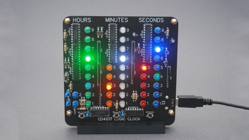
How is it a binary clock? To me, it appears that it has 10’s and 1’s places for the hours minutes and seconds that, and in this picture, reads exactly as printed: 6:36 and 57 seconds. Wouldn’t a binary clock actually display its time, in binary?
To be fair, “4017 Decade One Hot Encoding Clock” doesn’t quite have the same ring to it.
It’s a decimal clock, not binary. Also what’s “old-school” about these LEDs? That they aren’t surface mount?
It’s old school because there’s no raspberry pi involved, duh
The only old school part is that it use logic chips instead of the usual microcontroller/processor/RTC for the clock.
Old School LEDs …
You mean they don’t burn your retinas out when you drive them with 25mA ?
I remember LEDs like that. The only reason you know they are on is they aren’t quite as bright when yiu remove the power.
I can’t even remember where I got those floor sweepings, at a hamfest, but maybe elsewhere too. Imperfect cases, what seemed to be the wrong die in the package (so green die in a red colired package), and very weak output.
Year 2000 was 21 years ago, eye burning blue LEDs are Old School now :)
You guys are correct, nothing old school about 5mm LED’s, it’s old school because it uses 4000 series digital logic from start to finish. There’s no micro controller or Raspberry Pi involved. I’m cooking up a clock that does use a true binary coded decimal output. Believe me, this format is a lot easier to read!
The really old LEDs where red only, though you could alternatively drive a red LED in orange or yellow time limited modes for 3 and 2 ns respectively. LED color was often hard to identify after using these modes.
Where’s the binary part of this “binary clock”? This is just a decimal clock using the PCB as the label for each digit.
Neat PCB, but definitely not a binary clock, and not even BCD at that.
the individual LEDs are modulated with super low frequency binary waveforms so together they form a cluster that indicates time ;)
Anyway, if you want a (non computerized) BCD clock have a look at: http://www.bowdenshobbycircuits.info/clock.htm
What an awesome discrete decimal clock!
i want this product
You can get your hands on one here:
https://www.kickstarter.com/projects/1639195067/the-cd4017-decade-binary-clock
with that blue and white led it is very not retro, what we had back in the days was red, green and yellow…
That looks suspiciously similar to the clock I built. Only that I took about 3 weeks to build it (and it shows…)
The basic difference is my version uses mains frequency as a clock signal instead of a standard watch quartz and mine has an alarm… and LEDs for the zeroes.
https://hackaday.com/2020/08/10/breathtaking-alarm-clock-looks-like-it-came-from-a-1960-fallout-shelter/
That’s super cool! I like the look of those panel mount LED’s.
I would not use these resistor networks, just connect all anodes together and use one resistor, as only one LED will be showing at one time.
It’s a nice build!
that’s a really good idea. Thanks!
It’s a nice clock, but hackaday should know better than to repeat the designer’s mistake in calling it a “binary clock”. That has had a pretty well-established meaning for at least three decades. ThinkGeek has sold them, and see the January, 1991 issue of Popular Electronics for a kit (which I bought and built and still have running, btw :) ). https://worldradiohistory.com/Popular-Electronics-Guide.htm