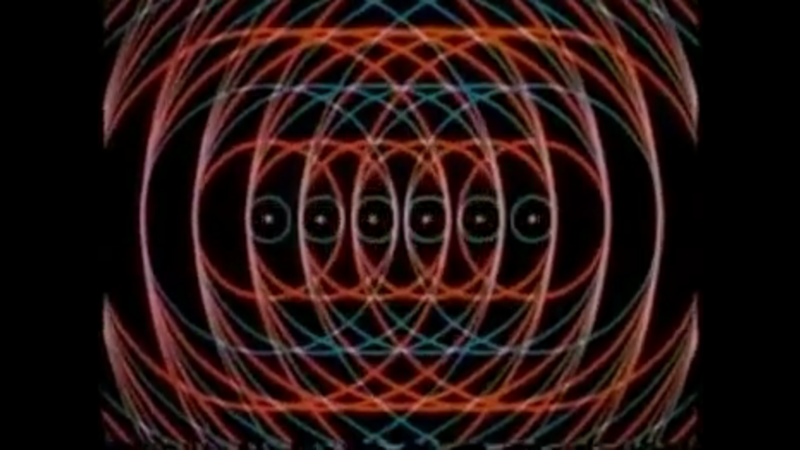
Back before the days of computers, animation was drawn by hand. We typically think of cartoons and animated feature films, but there were other genres as well. For example, animation was also used in educational and training films. [Javier Anderson] has tracked down a series of antenna and RF training videos from the Royal Canadian Air Force in the 1950s and 60s and posted them on his YouTube channel.
He has found three of these gems, all on the topic of antenna fundamentals: propagation, directivity, and bandwidth (the film on propagation is linked below the break). Casually searching for the names listed in the film’s credits will lead you down an endless and fascinating rabbit hole about the history of Canadian animation and the formation of the Canadian National Film Board and its Studio A group of pioneering young artists (one can easily lose a couple of hours doing said searches, so be forewarned). For these films that [Javier] located, the animator is [Kaj Pindal]. [Kaj] (1927-2019) was a Dane who learned his craft as a teenager, drawing underground anti-Hitler comics in Copenhagen until fleeing for his life. He later emigrated to Canada, where he had a successful career as an artist and educator.

Have you encountered any particularly helpful or well-made animated educational videos in your education and/or career? Are there any examples of similar but modern films made using computer generated images? Thanks to reader [Michael Murillo] for tipping us off to these old films.


These vids used some of the very first CGI: https://www.youtube.com/playlist?list=PL8_xPU5epJddRABXqJ5h5G0dk-XGtA5cZ
E field maximum, H field minimum and visa versa, happy to see that – it makes total sense to me.
But then later on in the video the electromagnetic wave propagation called “time phase space quadrature” the E field is at a maximum when the H field is also a maximum and both go to zero at the same time. That makes no sense to me, what am I missing, or failing to understand ?
i´d also like some clarity on this
\$E\$ and \$H\$ are usually in phase, like shown here https://en.wikipedia.org/wiki/Electromagnetic_field
Electric and magnetic field can alternate, that would make a circular polarized wave https://en.wikipedia.org/wiki/Circular_polarization
Usually, for linear polarized light, both E and H go to their max at once, not alternating.
I think the confusion arises because an electric dipole (antenna) has different fields.
1) the near field (which ist static, ~1/r^3, but only the E-field)
2) the induction field (prop to i/r^2, for the E- and H-field)
3) the far field (prop. to 1/r, for the E- and H-field)
(this omits the angular dependences, which contribute no phase shifts)
In the animation i think they show the electrostatic E-field and the induced magnetic H-field, which are 90 degrees out of phase (this is indicated by the i in the denominator for the H-field, i is the complex unit, a denotation for 90 degrees phase shift)..
The fields 1) and 2) don’t radiate, although they contain e.-m. field energy. Energy oscillates back and forth to the antenna, they are so called reactive fields (like in reactive or wattless currents).
The animation doens’t tell the whole truth. In this respect the animation is not really good. I have seen many similar animation or explanations which make most of the time a complete mess (if yount don’t believe: watch out on youtube). As Einstein said: Make the things as simple as possible, but not simpler. Electrodynamics is not as easy as some animations make you believe.
A remark about the mentioned circular polarisation:
In circular polarisation the two orthogonal components of the E-field are 90 degrees out of phase. However, this has nothing to do with the phase shift between the E- and H-field. Each of the orthogonal E-fields has his corresponding H-field, which is perfectly in phase with E (all statements for the far field).
Reference:
https://de.wikipedia.org/wiki/Hertzscher_Dipol (in German, unfortunately I cna’t find an English correspondence)
https://engineering.purdue.edu/wcchew/ece604f19/Lecture%20Notes/Lect25.pdf
Hope this clarified the things.
Thanks! Much, much apprechiated!
Charge separation creates an E field. Charge motion creates an H (or B) field. So in a dipole, where charge separation and charge motion are out of phase, the two fields are also out of phase. Because of the shape of the current and charge separation in a dipole, the electric field is shaped like the magnetic field around a solenoid (toroidal). The field strength of the dipole fields fall off with the cube of the distance from the dipole.
However, in a vacuum (away from charges), an E field is changed (in space) by a change (in time) in the H field, and an H field is changed (in space) by a change (in time) in the E field. The end result is that both change together and self-propagate, in phase. The field strength of these radiating fields fall off with the square of the distance from the dipole.
The part of the field which is driven by charges is the “near field”, and the part of the field which is driven by changing fields is the “far field”. Both exist throughout space, but because the near field falls off much faster than the far field, it doesn’t have a lot of influence in radio. It is used for things which are inductively coupled, like wireless charging, transformers, and the like.
I discovered these films some years back and have yet to find a better discription of how antennas and propagation work. Highly recommended.