In days of yore when solar panels weren’t dirt cheap, many people (and even large energy companies) used solar trackers to ensure their panels were always physically pointed at the sun to make sure they harvested every watt of energy possible. Since the price of panels has plummeted, though, it’s not economical to install complex machines to track the sun anymore. But all solar farms still track something else, called the Maximum Power Point (MPP), which ensures that even stationary panels are optimized for power production.
While small MPP trackers (MPPT) are available in solar charge controllers in the $200 range that are quite capable for small off-grid setups, [ASCAS] aka [TechBuilder] decided to roll out an open source version with a much lower price tag since most of the costs of these units are in R&D rather than in the actual components themselves. To that end, the methods that he uses for his MPPT are essentially the same as any commercial unit, known as synchronous buck conversion. This uses a specially configured switch-mode power supply (SMPS) in order to match the power output of the panels to the best power point for any given set of conditions extremely rapidly. It even works on many different battery configurations and chemistries, all configurable in software.
This build is incredibly extensive and goes deep into electrical theory and design choices. One design choice of note is the use of an ESP32 over an Arduino due to the higher resolution available when doing analog to digital conversion. There’s even a lengthy lecture on inductor core designs, and of course everything on this project is open source. We have also seen the ESP32 put to work with MPPT before, although in a slightly less refined but still intriguing way.
Thanks to [Sofia] for the tip!


great write up for this project, well worth the read..
agreed
This is phenomenal, and the documentation is a masterclass. Even if you don’t end up building an MPPT controller as a result of of this, you’re guaranteed to learn a bunch of super useful stuff from the write-up! I’m floored!
“every watt of energy”
*cringe*
*cringe also – low-key editors make that mistake again again and again -*
That´s what happens when one doesn´t have time but has power.
I like x WattHours per hour or x AmpHours per hour.
ah.. the acceleration of amphours!!
Hoping I/we can scale this down for smaller systems. They need it all the more. RVs & the like.
There are some very elegant solutions like the BQ25570 that harvest every single Joule from a smallish solar panel, buffers it in a supercapacitor, and pulse charges a battery. Perfectly adapted for low-power solar projects. check the CJMCU-2557 evaluation board. Worth every penny, plug and forget solution.
How familiar are you with this board? I’m struggling for documentation, or specs on what the CJMCU board is configured for. Did you have to change default resistor settings? I plugged the values from mine into the spreadsheet offered by TI and it seems it’s configured for a VBAT_OV of 4.066V and a VOUT of 2.5V so I might have to change those.
Good times attempting to build one of these. Worked great until reversed the phase angle of the control and started sending power from the batteries backwards through the controller into the source. Much smoke.
Had not spotted that the current couldn’t be turned all the way down in synchronous mode without risk of the thing acting as a buck converter pointing the wrong way. Was using a 24V battery as a source and a 12V battery as a load, so once reversed, there was nothing to stop the current going backwards. Then once the circuit was cooked, nothing but fuses to stop both batteries pouring magic smoke releasing agent into the circuit from each side.
Nope, he dealt with it (read the instructable, it’s quite clear), look at the Q1 resistor. Basically, this MOSFET is put in reverse direction (so when it’s off, its internal diode is in the wrong way, it’s not conducting, preventing the battery’s current to flow back to the solar panel).
It’s turned on by the MCU via an isolated DC/DC converter (so you don’t have a ground loop here, with a floating mosfet like this). It’s a nice design, I don’t know if it’s working in practice, but it seems to work in theory.
Couldn’t this be completely avoided through the use of blocking diodes? I thought this was the norm?
Amazing, and I wanted to build a psu mode version but I see it is there already! Would this turn it into a low voltage micro-inverter? That s what I want to do to have multiple panels connected via these units to run battery less straight into my loads via a parallel bus. I should make it all shade tolerant and avoid back feeding shaded panels whist extracting a few watts tat they can muster. Any thoughts?
Nice, I am in the process of planning installation of some solar panels on my roof. Since I am in SEE-NWW orientation I wish to know if it’s more economical to to est-west installation (since the converter has 2 mppt) or only SEE.
I plan to consume most of the energy myself as DIY route make preferential resell mostly impossible (although possible, but at below market price, meaning mostly nothing).
So I need to know if trading max production against longer production time is interesting or not (since I have a lot of piloted power sink available).
So I can probably hook two cells to pseudo mppt trackers and log for some time to check both scenario.
ESE and WNW?
Panel orientation . East south east & west north west
I also have some panels set up for experimentation at the moment. If you are using what (watt!) you make, then look at which times of day you use electricity, and angle the panels for each consumption period.
Other than that some battery store (for when you use the electric kettle say which needs more power for a short period) or you can dump the excess power into a hot water cylinder.
My brother uses his washing machine when the sun is out and his panels are generating.
I’ve got two primary sink: water heater and pool pump, the first is the one that need the peak power, but the later is the one that cost more in summer.
Given that the pool pump must run when sun output is high, it’s a natural sink.
The secondary sink is air-con, while not really mandatory where I live, it’s a nice thing to have when we can’t manage heat waves via passive handling.
I was thinking of putting a (directional) power meter of my own next to where the mains comes into the house (clamps on to the meter tails). Then when the power input from the grid becomes negative (I’m generating more than I need) I have a wireless link to my power sinks (in my case hot water) and they start drawing a matching power to keep it just about zero.
To do this with an immersion heater that normally might draw 4kW, the controller will incorporate a triac ‘dimmer’-like circuit so it just feeds in enough power to balance it all out.
If I start using something in the house, for example kettle, oven or shower, the immersion controller will of course automatically shut off until that extra draw disappears.
In your case you could do a time-of-day/year based draw at your power sinks so for example the pool pump only runs when you’re on a summer day, and your water heater when it’s winter, but naturally only when the generation is in excess.
CC BY-NC-SA 4.0 — sad license for such a good project.
At least FUGU firmware is true opensource, CC0-1.0.
Change one resistor and license no longer apply.
That’s not how it works, that’s not how any of this works.
“Older lady pins a photo to her ‘social media wall’ as more savvy friend looks on…”
This may work for CC BY, but it definitely doesn’t work for “-SA”, ShareAlike.
Lemme guess, the “no commercial” part?
Yep
Why? You want to get paid by commercializing this guy’s design?
No, I avoid to be a part of such projects: no use, no help, no contribution, no donations. And this is sad, because this project looks very good, except of license.
Caps are rated to max 5K-10K hrs, no where near 10years (break even point for solar).
Just wait for fussion power.
(Electrolytic) caps regularly can reach lifetimes of 10yrs or more. The key point is temperature. For every 10°C below the specified max. temp. lifetime doubles.
“The rated lifetime is measured by the capacitor’s manufacturer during stress testing and is usually shorter than the capacitor’s lifetime in an application.”
Keep you the temperature, voltage, and ripple current inside the parameters and it’ll last much longer.
Ripple current is going to be quite high in this application, I expect. But yes, over-specify the caps (higher voltage, 105C etc) AND go for the highest manufacturer’s lifetime quotes (20 or 30000 hours).
I have no intention of ever building one of these, but as always, I soaked up some worthy tidbits. Thanks!
I have a lot of respect for anyone who will take the time to be as informative as this guy is.
I thought “Maximum Power Point” was a really long slide presentation.
Battledecks or PowerPoint Karaoke?
https://battledecks.wordpress.com/guide/
Hackaday:
One design choice of note is the use of an ESP32 over an Arduino due to the higher resolution available when doing analog to digital conversion.
Nope!
A separate ADC is used (@03:50), and it’s mentioned at least twice in the video that it’s done to improve accuracy and reduce noise.
At first I was a bit put off by the high pace this video is edited on, but it’s amazingly chock full of info and still lasts 18 minutes, and it’s intentionally made in such a way that you can hit the pause button if you need more time to digest.
Good! Esp32’s ADC is incredibly noisy, so this statement in the article had me puzzled/worried.
Lots of math needed for MPPT?, no not actually. As long as one bounds the output voltage, while monitoring the output current, a simple comparison can do the trick . One can vary the PWM up and down, and select the one with the highest output current. The true power is of no real concern, we are just optimizing for the max power. In theory a simple op amp comparing the instantaneous output current compared with a smoothed history (low pass filtered) current can tell you if the newly selected PWM ratio is better or worse than the one you just moved from. It really is possible to build an MPPT using analogue only parts.
Nope.
You’re close but took a shortcut too many.
The maximum current will be when the solar panel is short circuited.
If you just limit acceptable voltage, but still only optimize for current, then it still will track to the lowest voltage you set, as that will yield maximum current.
But any silly microcontroller can multiply voltage and current to optimize the maximum power, and then wiggle PWM a bit around to optimize withing reasonable setpoints.
It can probably be done with an analog multiplier too, but the flexibility of a microcontroller lets you easily add al sort of control algorithms. And it does not have to be fast either. Fastest even is probably some clouds on a partly cloudy day, or the rare event of someone (or animal) casting a shadow over a solar panel.
Added safeties may have to act quicker, but for the basic MPPT a bif of slow wobling around the setpoint is proably enough.
You’re measuring the wrong current. Ignore the incoming current, measure the output current, now you can simply optimize for the max, no maths required.
main inductor 16 ga for 35A ?
core is down to 50% at 600 A-T or 16 turns around the coil at 35 A.
Description says 30 turns. So the core flux is down 50% 20A
Seems to small to me.
What do you fellows think?
Yes
Cool project!
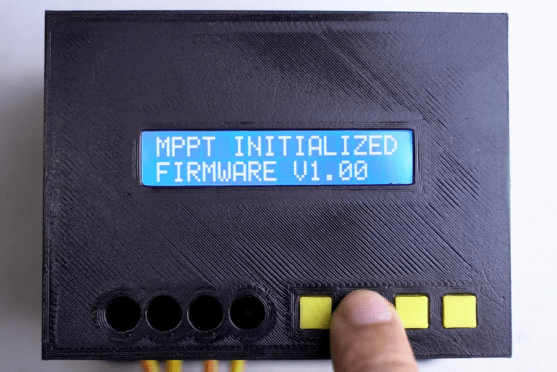
For the 3D printing gurus here, what causes the non-consistent gaps between the lines in the top surface (probably first layer of the actual print?) of the print shown in the title photo of this article? The reason I ask is that I get this in my own prints when I print with PLA. The lines in my PETG prints look much more even and consistent.
In my experience, defined lines on the first layer like that mean the nozzle is too high. PETG generally benefits from a slightly higher first layer, so that could explain why it goes down better with no adjustments to the hardware. You could try adjusting the nozzle height to find a happy medium, or else do a per-material Z offset in your slicer so PLA prints a little lower than PETG.