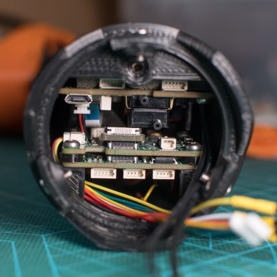
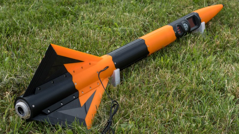
We’re delighted to see the progress on [Foaly]’s 3D-printed Cortex 2 rocket, and the latest build log is full of beautiful pictures and design details. Not only is this rocket jam-packed with an efficiency of electronics and smart design, but it almost seems out to single-handedly prove that 3D-printing is far from the novelty some think it is.

There is so much going on in the Cortex 2 that it simply wouldn’t be possible to do everything it does without the ability to make one’s own parts exactly to specification. In fact, there is so much going on that cable management is its own challenge.
Everything in the build log is interesting, but the design of the parachute system is of particular note. [Foaly]’s original Cortex rocket met it’s end when the parachute failed to deploy, and Cortex 2 is determined to avoid that fate if it can. For the parachute and any cords and anchors, a careful layout maximizes the chances of a successful deployment without anything tangling, but there are some extra features as well. The panel covering the parachute is mounted with the help of four magnets, which are mounted with opposing polarities. This provides an initial repulsing force when the door is unlocked by a servo, which should help wind immediately rush in to the opening to blow the panel away. The recovery system even has its own dedicated microcontroller and can operate autonomously; even if software for everything else crashes, the parachute will still get deployed. Locking connectors for all cables also ensure that acceleration forces don’t dislodge any contacts.
Everything about the rocket looks great, and the amount of work that has gone into the software is particularly evident. The main controller even has an interactive pre-flight checklist, which is a fantastic feature.
The last time we saw the Cortex 2 it was still only about half built, and we can’t wait to see how it performs. Rocketry is a field that has benefited greatly from things like 3D printing, the availability of highly-integrated electronics, and even such things as a rocket design workbench for FreeCAD. Better tools enable better work, after all.


Why all components and pcb are designed to experience maximum force at launch?
Why? Why else? So nothing gets dislodged during high-G events.
Really can’t see a problem with it being that way, the parts are all well attached to the PCB – no massive leverage parts sticking out heaps I can see, they don’t weigh anything much and the acceleration while its bound to be pretty high isn’t going to be worse than the sudden deceleration of dropping your phone etc onto the desk under normal use – the sort of forces that are not actually hard for solid state electronics to deal with. It is not like its a railgun ‘rocket’ launch system that might just put the full acceleration and go well into supersonic speeds in to a meter of barrel, its going to accelerate for some seconds over probably a hundred odd meters (not actually sure what rocket motor its using so those could be overestimates) till the motor burns out at a much more reasonable rate.
Plus any sensors on the PCB probably need to be rigidly mounted to actually report correctly.
As you can probably guess : because it made the integration a lot easier this way. A stack of horizontal circular PCBs is possible, I’ve done it in a previous rocket, and it is indeed better when you consider very high accelerations, but routing is a pain. You lose a lot of space to the connectors linking the PCBs together. This especially true here because the internal diameter is pretty small. Also, the front panel (display, buttons, …) lends itself a lot better to a vertical PCB. The relatively low power-to-weight ratio of these rockets means that they experience relatively low G’s, (unlike, as Foldi-One pointed out, some kinds of railguns or supersonic missiles), around 15 to 20 g’s. These kind of CMS parts can easily survive that.
The internals for the rocket are overkill. Also, a user interface and GUI built into the rocket itself?! Since this thing is all custom, I can’t help but think there should be a single PCB and MCU, a small program written in assembly, and use a UART interface.
Maybe I’m just old but to me, less is more.
Being fun to use is probably the most important spec for hobby rockets. Some people enjoy using connectors and serial terminals, others like a simple self-contained rocket. I think the latter would at least be easier to dig out after a few years of storage and figure out how to use again :)
Not from BSP.space ?
One of the most basic things for anything that flies has been somewhat neglected here, namely weight savings. I see metal screws and connectors, the boards have large unused spaces, etc. I have noticed this in recent times, that people overkill on the computer side of things, and then lack the skills on the mechanics side. A while back there was a project where a young guy wanted to launch a high altitude balloon, and the internals were total overkill, but the balloon did not take off because it was too heavy/not big enough. While I really applaud such projects, esp. when youngsters do it, it just shows (to me) that there is a blatant lack of basic knowledge and skills. Computers won’t beat the physics for you.
There is flies, and then there is race car levels of expensive to build and repair even the most basic parts, but that puts it right at the peak of performance..
I expect this thing will work very well (seems they have taken COM and COP into account in the design so it should), yeah its heavier than it needs to be so won’t get nearly as high/fast, but then it aught to be easier to keep flying for it. Engineering compromise… The one thing on it I don’t get is why the screen, button etc are integrated seems like the perfect thing to connect up preflight, do the checklist and disconnect, but there is no denying it gives it a rather interesting and unique look.
While I agree with you about weight optimization in the general case, it was not the concern here. The launch area for this category of rockets is not very large and there is a constraint on the distance they can go (200m max ballistic impact distance), which translates into a minimum weight allowed (around 1.3~1.4kg, depending slightly on some other parameters that affect aerodynamic drag). This minimum weight was my target, and I ended up achieving it pretty well since I was simulated at 204m. I could have added about 30g of inert mass to the rocket to fall into the bounds, but I was given a exemption and was able to fly as-is thanks to favorable meteorological conditions.
It’s a hobby rocket though, not a DARPA project… The only goal here is to have fun. Can we not appreciate the time and work that went into this hobby project?
Thanks for the article Donald. For those wondering, the rocket did fly this summer, and performed successfully. The landing was a bit rough though (that’s the problem with a smaller parachute), and a part of the fuselage broke on impact. But the nice thing about 3D-printed designs is that I only need to print that part again and the rocket is good as new. I’ll post a detailed review of the flight when I find some time to write it.
Can I buy the stls off of you? Only for personal use i won’t sell or distribute the files or printed parts