When you need to record the angle of something rotating, whether it’s a knob or a joint in a robotic arm, absolute rotary encoders are almost always the way to go. They’re cheap, they’re readily available, and it turns out you can make a pretty fantastic one out of a magnetic sensor, a zip tie, and a skateboard bearing.
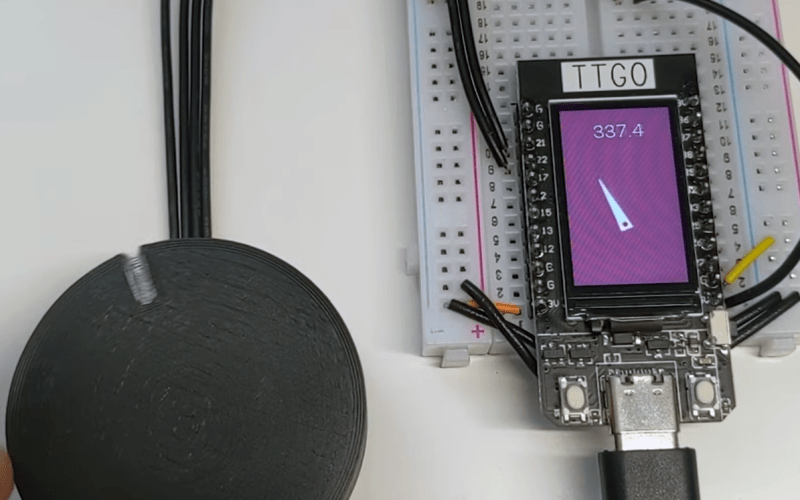
When [Scott Bezek] got his hands on a AS5600 magnet sensor breakout board, that’s just what he did. The sensor itself is an IC situated in the middle of the board, which in Scott’s design sits on a 3D-printed carrier. A bearing mount sits atop it, which holds — you guessed it — a bearing. Specifically a standard 608 skateboard bearing, which is snapped into the mount and held securely by a zip tie cinched around the mount’s tabs. The final part is a 3D-printed knob with a tiny magnet embedded within, perpendicular to the axis of rotation. The knob slides into the bearing and the AS5600 reads the orientation of the magnet.
Of course, if you just wanted a rotary knob you could have just purchased an encoder and been done with it, but this method has its advantages. Maybe you can’t fit a commercially-available encoder in your design. Maybe you need the super-smooth rotation provided by the bearing. Or maybe you’re actually building that robotic arm — custom magnetic encoders like this one are extremely common in actuator design, and while the more industrial versions (usually) have fewer zip ties, [Scott]’s design would fit right in.


It’s a 3D printed knob, not a 3D printed encoder. But you knew that…
Using this logic a friend of mine made some nice wooden potentiometers….
Absolutely fantastic!
Reminds me a Wang terminal very long ago.
Potentiates get dusty and noisy after time.
This Wang terminal solved this problem in an interesting way.
Instead of pots for brightness and contrast controls it had a pilot light that shone through movable filter strip that had a gradient from clear to black and on the other side was a LDR (light sensor). The brightness and contrast controls moved the filter.
well, the strip can get dirty, or maybe the pilot light can degrade. But that’s really nice
The knob is actually a functional part of the encoder. It contains the rotating magnet. Take it away and you don’t have an encoder.
I rate this as a 3D printed encoder.
And I think it is absolutely wonderful too.
The function performed is to encode the position of the knob (which is apparently 3D printed).
So if we refer to the knob by it’s function we would call it an encoder knob. The relevance of the fact that it was 3D printed is lost when we refer to it as a function rather than an object.
It is therefor a first class function (citizen).
I suppose since our bodies are full of and dependent upon all sorts of bacteria and other non-human life there are no real humans?
Only dead ones.
Also: https://hackaday.com/2021/03/05/magnetic-angle-sensor-mods-make-encoder-better-for-blasting/
How to build an absolute encoder:
step 1: buy an absolute encoder
step 2: print a knob for it
step 3: ???
step 4: claim that you “printed an absolute encoder”
I was expecting some new idea for an absolute encoder, not basically buying one.
Then I bet you were pretty disappointed.
I know I was
“3d printed user interface uses absolute magnetic encoder” would have been a more accurate title and include just as many buzz words
An absolute encoder chip without a knob, magnet, and rotating axis is a pretty shit self contained user controllable encoder. Or perhaps you make the chips you use in your projects out of sand and forgo buying commercial off the shelf components since that would make it not a new idea in your book?
BTW: The cap sense PCB are parts 5, 6 in here:
http://elm-chan.org/works/vlp/r9/galparts.jpeg
Too harsh for my tastes. Last time I built an absolute encoder, I did a lot of thinking and designing to make use of beam interruption sensors salvaged from laser printers to get three bits of directional data. A lot of work for a relatively mediocre result, compared to what’s possible if you know about the AS5600 sensor. Big if.
So if you already know about these sensors, good for you! But if you’re like me and are (haphazardly) self-taught, then THANK YOU SCOTT for growing my toolkit!
I kind of expected a 3d printed disk with binary holes and some kind of led phototransistor thing from the headline.
Same here. I clicked because I was curious how it was made an absolute encoder not just an incremental encoder using stat type of methodology.
Totally adding some of these modules to my stash. Design is simple and awesome. Am curious though. I don’t know magnetics well. How susceptable would these be to magnetic inference from, say, a nearby motor running on the same axis?
Magnetics is an inverse square relationship. So the magnetic force would have to be extremely close or extremely powerful to have a significant effect,
That being said, this sensor is 12 bit so in some cases there may be minor interference. It may for instance make the difference between 183.47 degrees and 183.46 degrees. In most usage cases that’s not going to be a problem.
Servo motors also use magnetic encoders, so I suspect it will be much of an influence to the accuracy.
I have some of their AMS5047 incremental encoders that I have used in the head of a milling machine (on a pulley adjacent to a 5hp 3ph motor) and on nema23 steppers and neither have much trouble. They seem to do some auto scaling of the signal so if you have trouble a bigger magnet on your sensor will usually drop the noise out.
Same principle used in Tesla’ steering wheel: https://youtu.be/KWA3IjSqIzk
Why not design the bearing mount to be a friction fit like the knob? I did with mine, and also used a short spring and a small ball bearing, along with a scalloped inner edge to make it a detented encoder